Eureka AIR delivers breakthrough ideas for toughest innovation challenges, trusted by R&D personnel around the world.

Control system of rotating end of CT system

A control system and rotary end technology, applied in general control systems, program control, computer control, etc., can solve the problems of high bus operation load, unstable communication, and many CAN bus messages, and improve stability, reduce CAN commands and message, the effect of reducing transmission

Pending Publication Date: 2020-06-19
FMI MEDICAL SYST CO LTD
View PDF0 Cites 0 Cited by
  • Summary
  • Abstract
  • Description
  • Claims
  • Application Information

AI Technical Summary

Problems solved by technology

[0002] At present, the CT system controls the operation of the rotating end mainly through the stationary end after receiving the software instructions of the upper computer, and then sending them to the rotating end through the CAN bus through the slip ring for control. The instructions of the rotating end are sent by the upper computer and receive the feedback information of the rotating end. A large number of CAN commands and CAN messages are transmitted on the process slip ring, resulting in a large bus operation load, resulting in unstable communication and affecting the stability of the system
The transmission rate of the CAN bus in this process is 1M / s, and the fastest sending time of a single command is 1ms. This control has low real-time performance and cannot realize control with high real-time requirements.
[0003] In the prior art, a single instruction is also used to replace the original two or more instructions. This solution can reduce the number of certain instructions, but there are still many messages on the CAN bus overall, which will still affect the stability of the system.

Method used


Image

  • Control system of rotating end of CT system
  • Control system of rotating end of CT system
  • Control system of rotating end of CT system

Examples


Embodiment Construction

[0015] In order to make the technical means of the present invention and the technical effects that can be achieved more clearly and more perfectly disclosed, an embodiment is provided hereby, and the following detailed description is given in conjunction with the accompanying drawings:

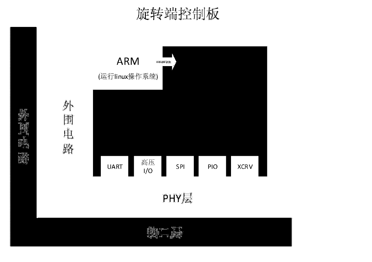
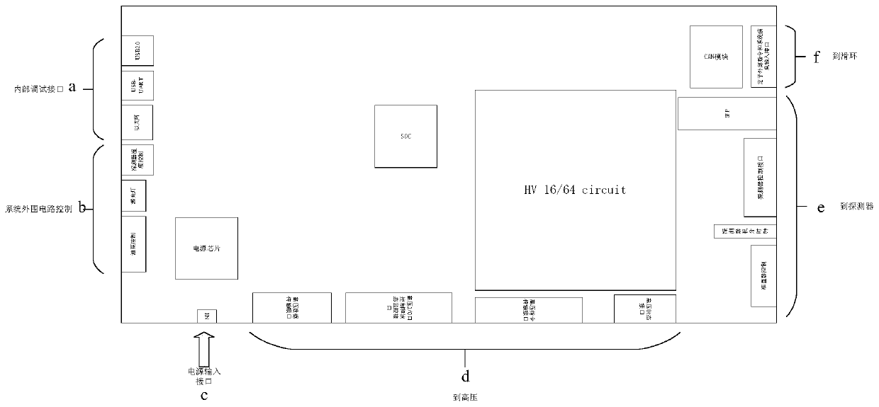
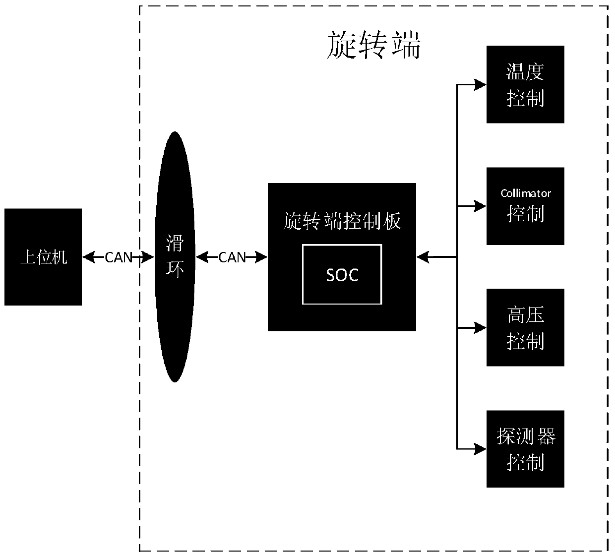
[0016] Such as Figure 1 to Figure 3 As shown, the control system of a rotating end of a CT system in this embodiment includes a host computer, a slip ring connected to the upper computer through a CAN bus, and a rotating end control board connected to the slip ring through another CAN bus; the rotating end control The board is connected to control the CT rotating end; the main control chip of the rotating end control board adopts the SOC chip containing the ARM part; the ARM part of the SOC chip runs the control logic, and the rotating end control board automatically runs the control command, sends the control command to the logic and receives the rotating end. feedback. The SOC chip descri...


PUM


Abstract

The invention provides a control system of the rotating end of a CT system, and relates to the technical field of CT equipment. The control system includes a host, a slip ring connected to the host through a CAN bus, and a rotating end control panel connected to the slip ring through another CAN bus; the rotating end control panel is connected to a control CT rotating end; the main control chip ofthe rotating end control panel adopts an SOC chip; the SOC chip is an integrated circuit formed by ARM and FPGA; the ARM part of the SOC chip operates control logic; and the rotating end control panel automatically operates control instructions, sends the control instructions to the logic and receives the feedback of the rotating end. The FPGA chip of the rotating end control panel is replaced into the SOC chip; the logic controlling the rotating end on the host is placed on the SOC to operate; the host sends start, interrupt and end instructions, and the rest rotating end control instructions are automatically operated by the rotating end control panel; and therefore, CAN instruction and messages can be greatly reduced, the distributed control of the CT system can be formed, and the operation stability of the CT system can be greatly enhanced.

Description

technical field [0001] The invention relates to a control system for a rotating end of a CT system, belonging to the technical field of CT equipment. Background technique [0002] At present, the CT system controls the operation of the rotating end mainly through the stationary end after receiving the software instructions of the upper computer, and then sending them to the rotating end through the CAN bus through the slip ring for control. The instructions of the rotating end are sent by the upper computer and receive the feedback information of the rotating end. A large number of CAN commands and CAN messages are transmitted on the process slip ring, resulting in a large bus operation load, which leads to unstable communication and affects the stability of the system. The transmission rate of the CAN bus in this process is 1M / s, and the fastest sending time of a single command is 1ms. This control has low real-time performance and cannot realize control with high real-time...

Claims


Application Information

Patent Timeline
Patent Type & Authority Applications(China)
IPC IPC(8): A61B6/03G05B19/042
CPCG05B19/0423A61B6/032A61B6/54A61B6/56G05B2219/25257
Inventor 朱炯贺崇煊陈修儒倪健王武斌黄振强
Owner FMI MEDICAL SYST CO LTD
Why Eureka
Eureka Blog
Learn More