
Mathematical model calculation device and control device of rolling production line

A mathematical model and computing device technology, which is applied to rolling mill control devices, complex mathematical operations, program control, etc., can solve problems such as the reduction of mathematical model prediction accuracy

Active Publication Date: 2022-03-22
TOSHIBA MITSUBISHI-ELECTRIC IND SYST CORP
View PDF12 Cites 0 Cited by
  • Summary
  • Abstract
  • Description
  • Claims
  • Application Information

AI Technical Summary

Problems solved by technology

Therefore, when the tension is dynamically changed among the racks, the prediction accuracy of the mathematical model decreases.

Method used


Image

  • Mathematical model calculation device and control device of rolling production line
  • Mathematical model calculation device and control device of rolling production line
  • Mathematical model calculation device and control device of rolling production line

Examples


Embodiment approach 1

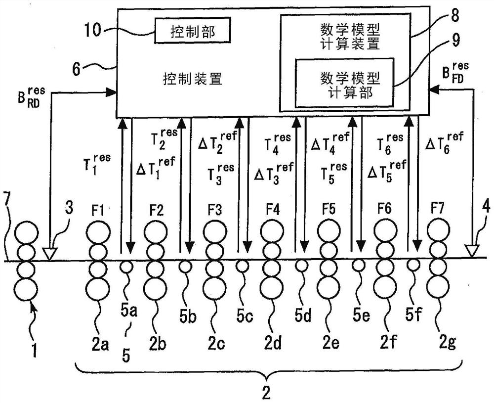
[0027] figure 1 It is a configuration diagram of a hot rolling production line for a mathematical model calculation device of the rolling production line in the first embodiment.

[0028] Such as figure 1 As shown, the hot rolling production line includes a thick rolling mill 1, a finishing mill 2, a thick mill output side plate width instrument 3, a finishing mill output side panel wide instrument 4, a looper device 5, and a control device 6.

[0029] The thick rolling mill is provided on the output side of the heating furnace (not shown). The finishing mill 2 is disposed on the output side of the rough mill 1. The finishing mill 2 has a plurality of racks. Multiple racks are arranged in the horizontal direction. For example, a plurality of frames are composed of a frame 2a, a rack 2b, a frame 2c, a frame 2d, a frame 2e, a frame 2f, and a frame 2G. The rough mill output side plate width instrument 3 is disposed on the output side of the rough mill 1 and the input side of the fin...

Embodiment approach 2

[0114] Figure 11 Illustrative of the application of a control block diagram of the embodiment of the rolling line of the rolling line mathematical model of computing device 2. Further, the same are given the same or corresponding portions of the embodiment 1 for reference numerals. Description thereof is omitted.

[0115] In Embodiment 2, the control device 6 includes a compensator 11 Smith. Smith compensator 11 the line (command value) changes a reference value for the tension between the frame Negative feedback to the PI controller. Further, the control means 6 through a further line to the delivery side of the finishing mill side wide width gauge prediction value from the finishing stand 4 by the transfer delay due to the waste of time Also negative feedback to the PI controller. At this time, if the output of the mathematical model based on the finishing mill side prediction value width There is an error, the error is input to the PI controller online.

[0116] According t...


PUM


Abstract

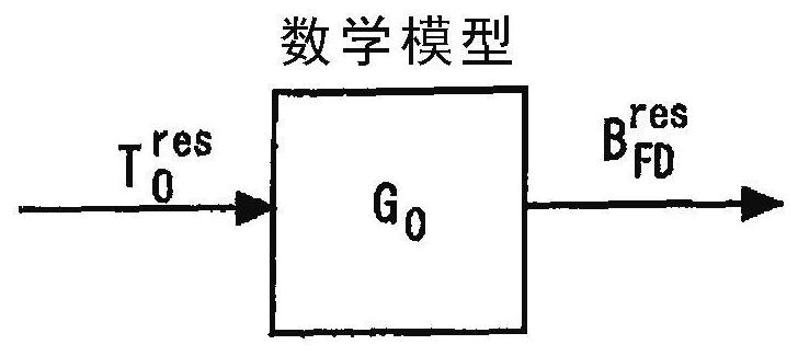
The present invention relates to a mathematical model calculation device of a rolling production line and a control device of a rolling production line. set to control the tension of the rolling material, thereby controlling the strip width of the rolling material on the output side of the finishing mill, the mathematical model calculation device has a mathematical model calculation part, and the mathematical model calculation part is for the rolling production line, Based on the history of the response value of the rolling line, the response value of the tension of the rolled material between adjacent stands is used as an input, and the response value of the strip width of the rolled material on the exit side of the finishing mill As output, the mathematical model is calculated.

Description

Technical field [0001] The present invention relates to a mathematical model calculation device and a control device for rolling production lines. Background technique [0002] Patent Document 1 discloses a control device for rolling production lines. The control device controls the plate width of the rolling material on the output side of the finishing mill based on the mathematical model calculated by linear recursive. [0003] Prior art literature [0004] Patent document [0005] Patent Document 1: Japanese Laid-Open No. 2003-211211 [0006] However, in the control device described in Patent Document 1, the mathematical model is obtained by a stable state. Therefore, in the case where the tension is dynamically changed during each rack, the predicted accuracy of the mathematical model is lowered. Inventive content [0007] The present invention is made in order to solve the above problems. An object of the present invention is to provide a mathematical model calculation devi...

Claims


Application Information

Patent Timeline
Patent Type & Authority Patents(China)
IPC IPC(8): B21B37/00B21B37/22G06F17/11
CPCB21B37/00B21B37/22G06F17/11Y02P90/02G05B19/41885B21B37/48G06F17/10G05B23/024G05B23/0254
Inventor 铃木敦
Owner TOSHIBA MITSUBISHI-ELECTRIC IND SYST CORP
Learn More