Machine housing and rotating shaft assembling device

A technology for assembling equipment and casings, applied in the field of casing and shaft assembly equipment, can solve problems such as low efficiency and uneven dispensing, and achieve the effects of reducing noise pollution, good product consistency, and improving working environment.

Pending Publication Date: 2020-06-19
深圳市龙德自动化系统有限公司
View PDF0 Cites 0 Cited by
  • Summary
  • Abstract
  • Description
  • Claims
  • Application Information

AI Technical Summary

Problems solved by technology

[0006] The purpose of the present invention is to provide a casing and shaft assembly equipment. The technical solution provided by the invention solves the technical problems of uneven glue dispensing, low efficiency and certain danger in the existing casing and shaft assembly method.

Method used


Image

  • Machine housing and rotating shaft assembling device
  • Machine housing and rotating shaft assembling device
  • Machine housing and rotating shaft assembling device

Examples


Embodiment 1

[0035] For the motor with outer rotor structure, its rotating shaft is fixedly arranged with the casing. The existing technology is to manually put the rotor casing and the rotating shaft on the press-fitting mold, and manually apply glue to the corresponding position of the shaft before putting the shaft. It is not uniform, and a 1-ton hydraulic press is used for press-fitting. There is no isolation between the operator and the press-fitting mold, and there is a certain degree of danger.

[0036] In order to solve the above technical problems, this embodiment provides a casing and shaft assembly equipment, the casing and shaft assembly equipment is based on the existing press-fit structure, adding automatic feeding, retrieving and dispensing mechanisms , which can realize the automatic operation of feeding, dispensing, pressing and retrieving, and isolate the possible damage to the human body caused by the press. The following diagrams are used to illustrate:

[0037] Such a...

Embodiment 2

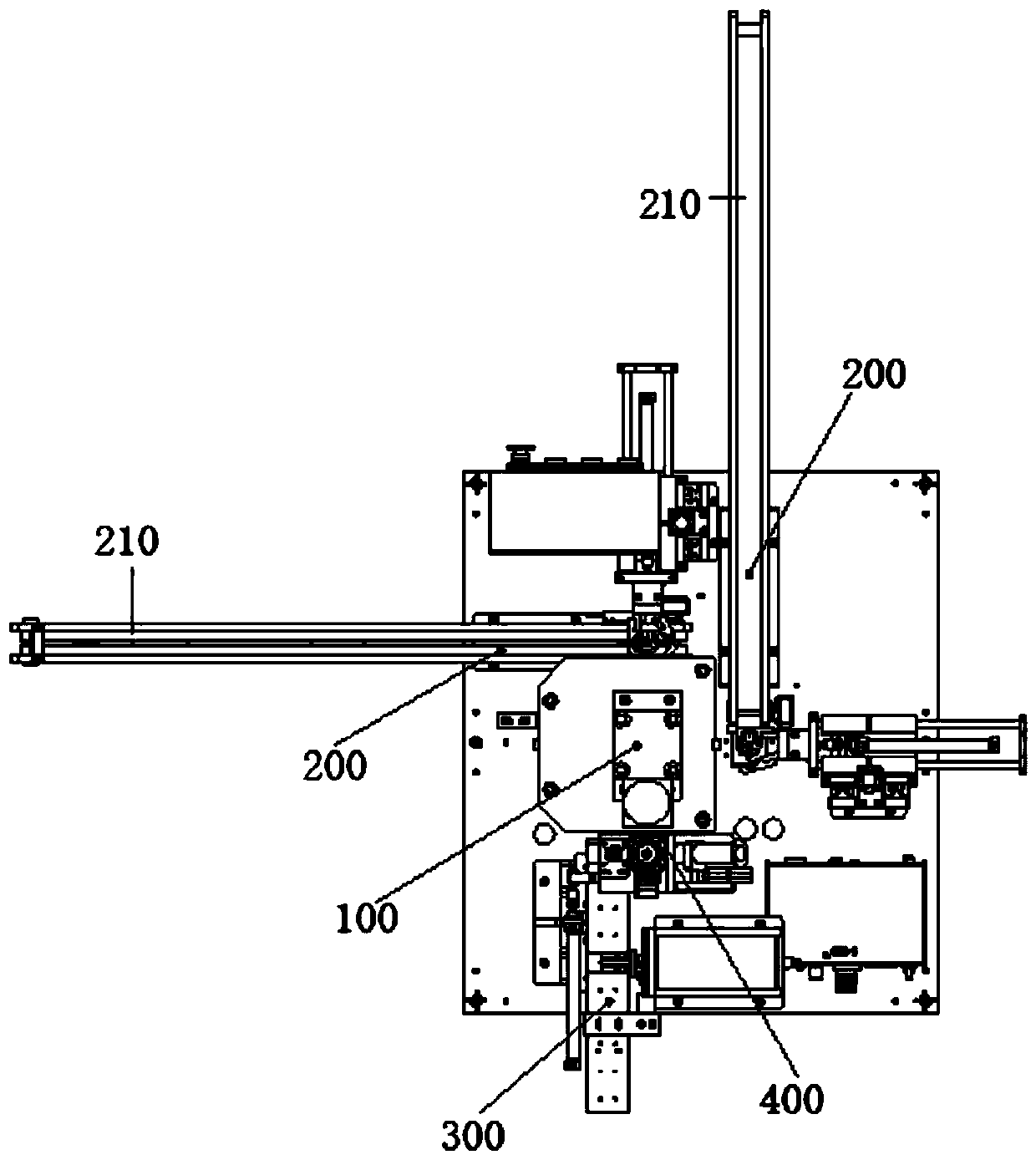
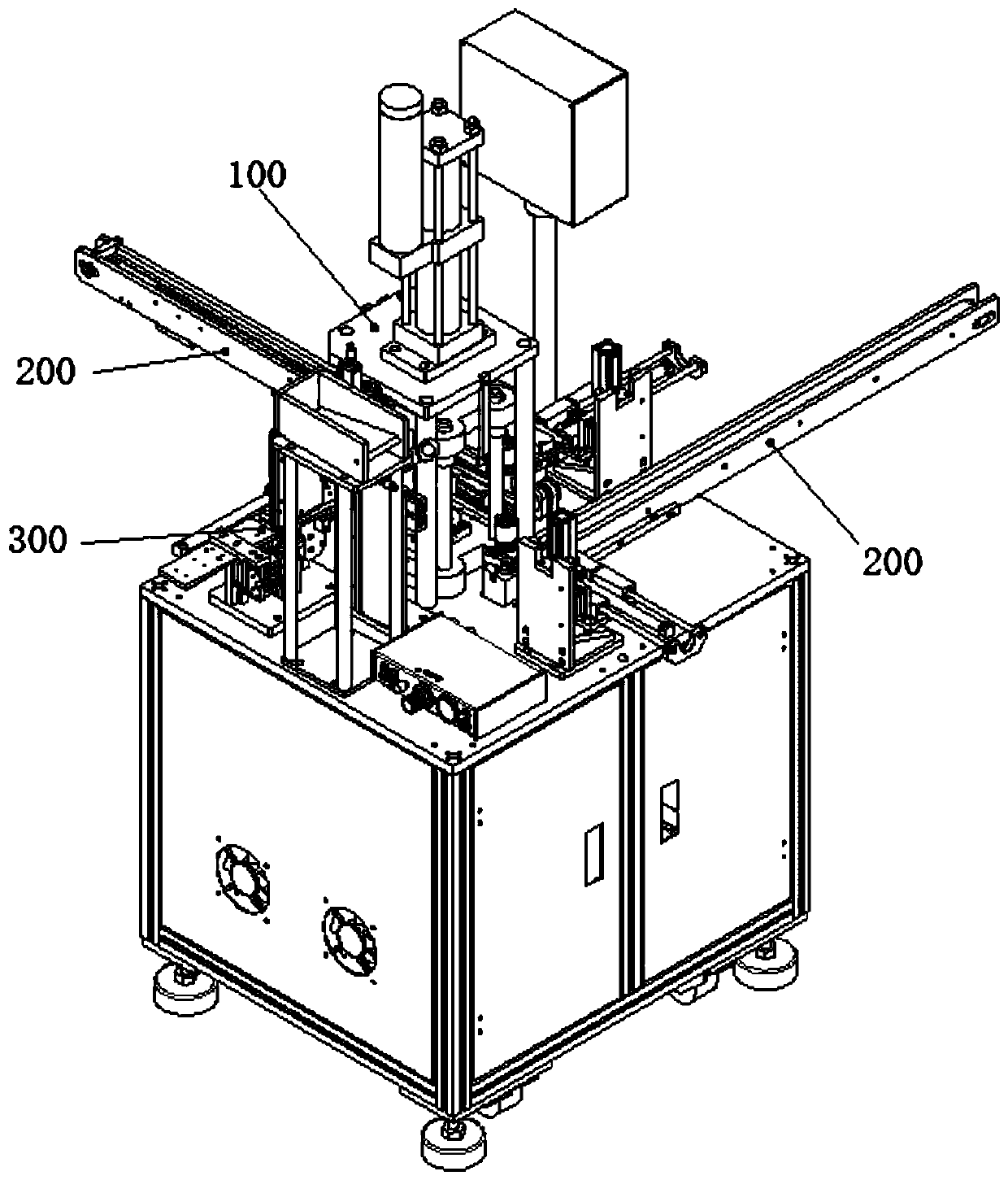
[0054] Such as Figure 1-2 As shown, the casing and shaft assembly equipment provided in this embodiment also includes a press-fit structure 100 for pressing the shaft, and two sets of casing transmission structures 200, shaft delivery structures 300 and point fittings arranged around the press-fit structure 100 Glue structure 400.

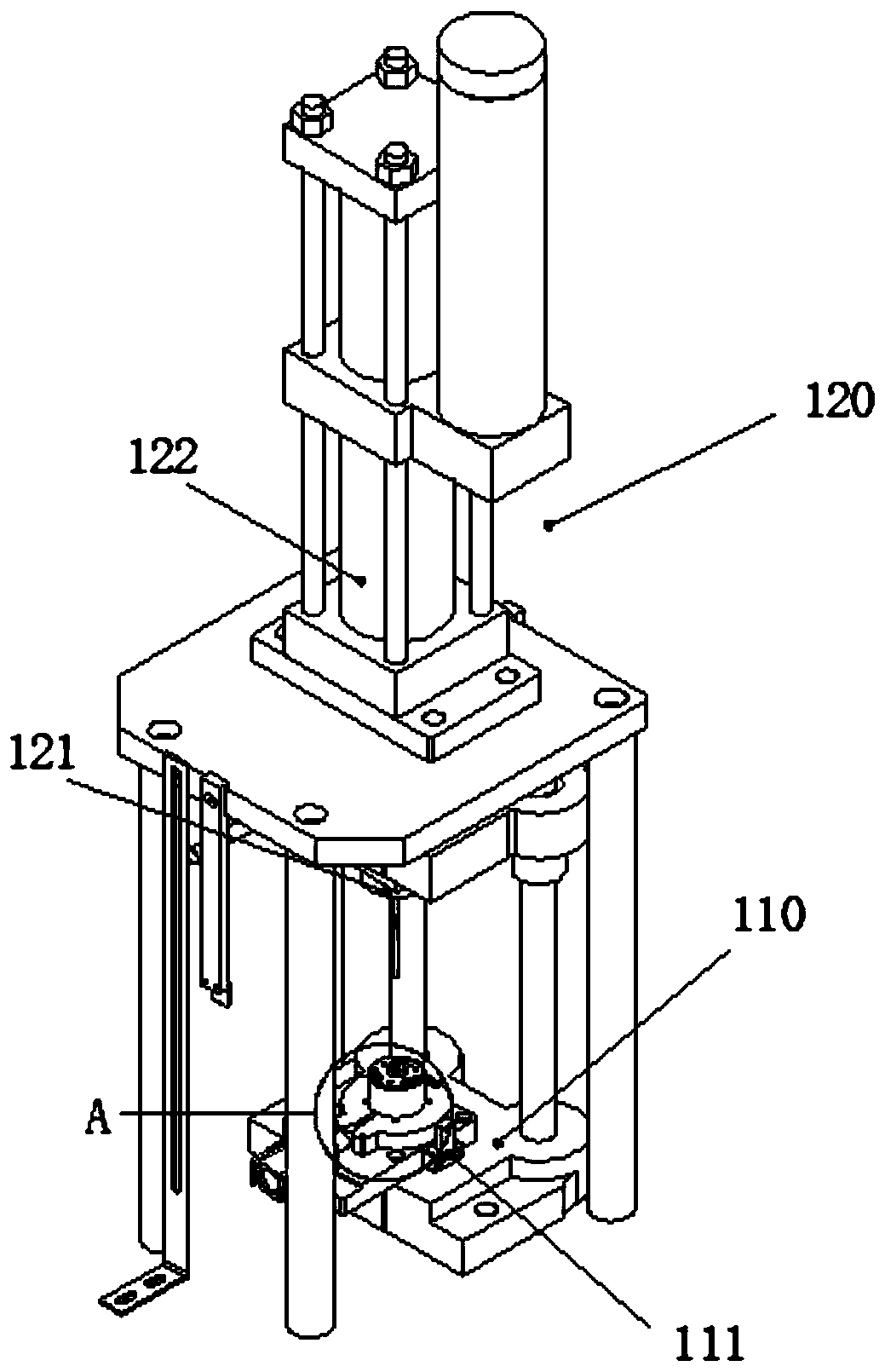
[0055] The shaft feeding structure 300 provided in this embodiment includes a shaft hopper 310 with a bottom vertical output shaft and a shaft feeding assembly 320 located below the shaft hopper 310 and used for clamping the shaft to extend between the pressing assembly 120 and the base 110 .

[0056] The shaft sending assembly 320 of the shaft sending structure 300 includes a second pneumatic finger 321 and a second two-axis transmission component 322 composed of a lifting cylinder and a traverse cylinder. After the rotating shaft falls from the shaft hopper 310, the lower end of the rotating shaft is exposed to the end of the blanking channel 3...

Embodiment 3

[0061] Such as Figure 1-2 As shown, the casing and shaft assembly equipment provided in this embodiment also includes a press-fit structure 100 for pressing the shaft, and two sets of casing transmission structures 200, shaft delivery structures 300 and point fittings arranged around the press-fit structure 100 Glue structure 400.

[0062] The shaft feeding structure 300 provided in this embodiment includes a shaft hopper 310 with a bottom vertical output shaft and a shaft feeding assembly 320 located below the shaft hopper 310 and used for clamping the shaft to extend between the pressing assembly 120 and the base 110 .

[0063] The shaft sending assembly 320 of the shaft sending structure 300 includes a second pneumatic finger 321 and a second two-axis transmission component 322 composed of a lifting cylinder and a traverse cylinder. After the rotating shaft falls from the shaft hopper 310, the lower end of the rotating shaft is exposed to the end of the blanking channel 3...


PUM


Abstract

The invention relates to the technical field of rotating shaft assembling, and particularly relates to a machine housing and rotating shaft assembling device. The machine housing and rotating shaft assembling device comprises a press-fitting structure used for pressing a rotating shaft, two machine housing conveying structures, a shaft conveying structure and a dispensing structure, wherein the two machine housing conveying structures, the shaft conveying structure and the dispensing structure are arranged around the press-fitting structure. The invention aims to provide the machine housing and rotating shaft assembling device. By the adoption of the technical scheme, the technical problems that an existing machine housing and rotating shaft assembling method is uneven in dispensing and low in efficiency and has certain danger are solved.

Description

technical field [0001] The invention relates to the technical field of rotating shaft assembly, in particular to a casing and rotating shaft assembly equipment. [0002] technical background [0003] The motor generally consists of a casing assembly, a rotor assembly, and an end cover assembly. The casing assembly includes a casing and a magnet fixed in the casing. The magnet is installed on the inner wall of the casing, and the magnet is fixed by two slingshots. [0004] In a conventional brushed DC motor, the stator field is on the outside of the housing and the rotor armature is inside the housing. After the brushless DC motor appeared, the rotating armature went from the inside to the outside, from the rotor to the stator; and the stationary permanent magnet of the stator went inside, from the stator to the rotor. This structure is called "outer rotor structure" or "inner stator structure". [0005] For the motor with outer rotor structure, its rotating shaft is fixed...

Claims


Application Information

Patent Timeline
Patent Type & Authority Applications(China)
IPC IPC(8): B23P19/027B23P19/00B05C5/02B05C13/02
CPCB05C5/0208B05C13/02B23P19/001B23P19/027
Inventor 宋炜强杨树球李永胜冯松友杨泽发
Owner 深圳市龙德自动化系统有限公司
Why Eureka
Try Eureka