Medical intravascular implantation device

A technology for implanting devices and blood vessels, applied in medical science, stents, surgery, etc., can solve problems such as anastomotic stenosis of internal fistulas, and achieve the effects of preventing anastomotic stenosis of internal fistulas, preventing vascular cavity stenosis, and improving compliance.

Active Publication Date: 2020-07-17
THE FIRST AFFILIATED HOSPITAL OF MEDICAL COLLEGE OF XIAN JIAOTONG UNIV
View PDF14 Cites 0 Cited by
  • Summary
  • Abstract
  • Description
  • Claims
  • Application Information

AI Technical Summary

Problems solved by technology

[0004] In order to solve the problem of stenosis of internal fistula anastomosis caused by venous intimal hyperplasia, the present invention provides a medical intravascular implantation device

Method used


Image

  • Medical intravascular implantation device
  • Medical intravascular implantation device
  • Medical intravascular implantation device

Examples


Embodiment

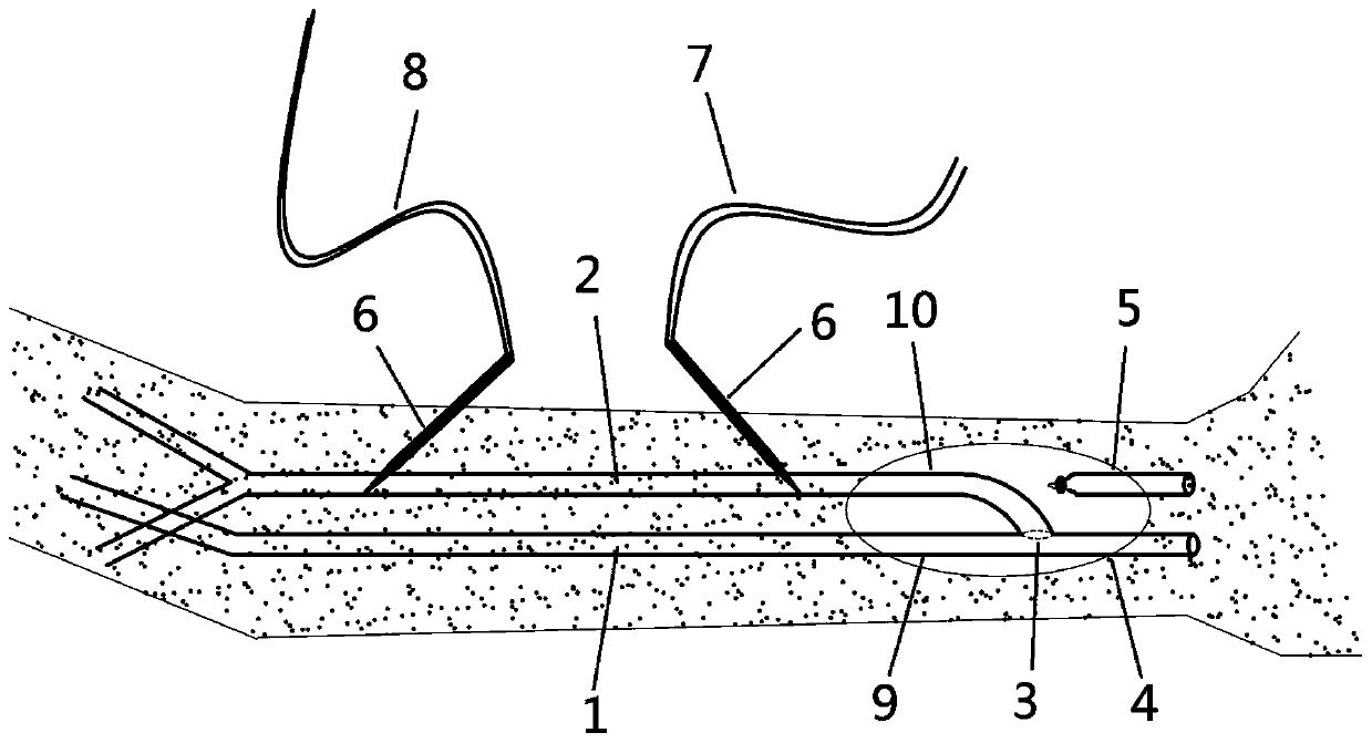
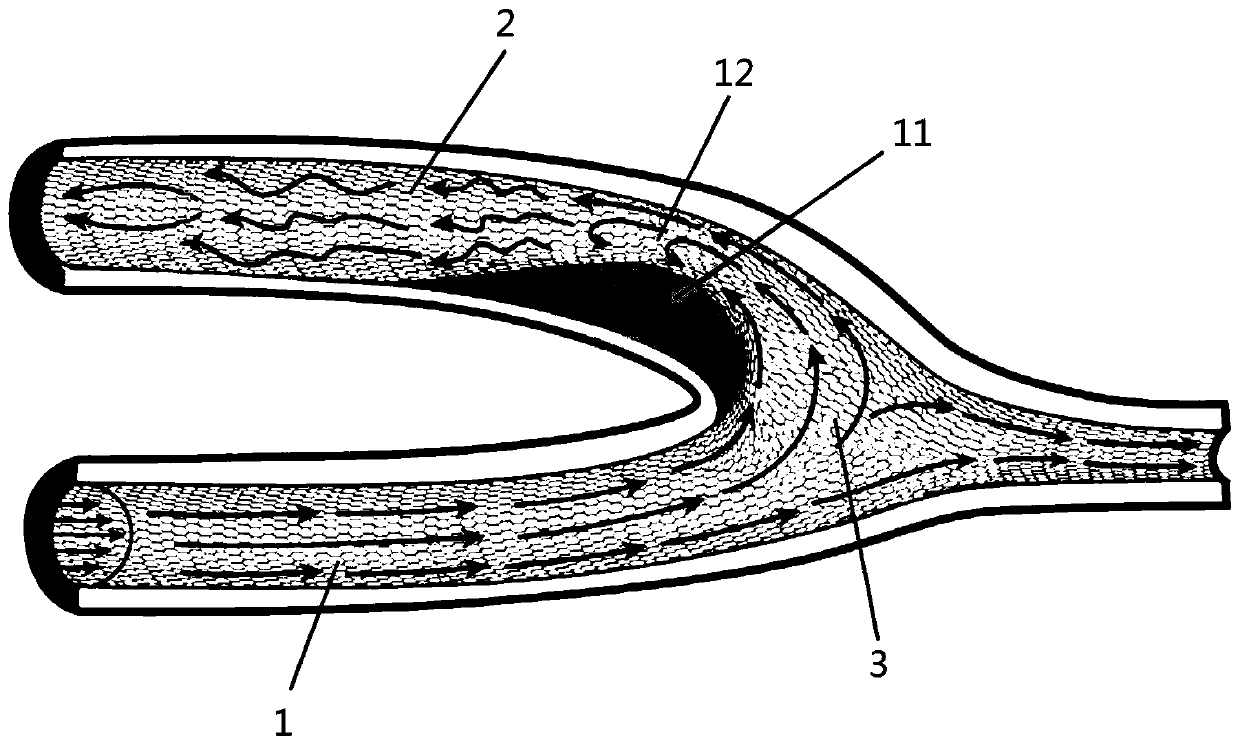
[0026] When performing internal fistula surgery, a 3 cm long longitudinal incision was made on the wrist of the patient after local infiltration anesthesia, the subcutaneous tissue and fascia were separated, and the radial artery 1 and cephalic vein 2 were freed. Block the blood flow at the proximal end 10 of the vein with a blood vessel clamp, ligate the distal end 5 of the vein with silk thread, cut off the cephalic vein 2 at the proximal end of the ligation point, and rinse the lumen of the stumped end of the cephalic vein 2 with heparin saline. The dissociated radial artery 1 is clamped with two vascular clips respectively at the proximal end 9 of the artery and at the distal end 4 of the artery to block the blood flow. A section of artery was reserved between the two vascular clips, and a 6mm long longitudinal incision was made on the side wall of this section of artery, and the lumen of the artery was flushed with heparin saline. Next, the device is implanted, and the pi...


PUM


Abstract

The invention discloses a medical intravascular implantation device. The medical intravascular implantation device comprises a pipeline and a flange arranged on the circumference of one end of the pipeline. The device related to by the invention comprises the pipeline and the flange; the pipeline consists of an expanded polytetrafluoroethylene (ePTFE) lining in an inner layer and a nickel-titaniumalloy net in an outer layer, and the flange is formed by extending the ePTFE lining at one end of the pipeline and turning the ePTFE lining to the periphery to be oval. During operation, the device is implanted into an internal fistula, the pipeline is positioned at the vein side of an anastomotic stoma, and the device has the effects of isolating blood flow shearing force and supporting the blood vessel cavity. The flange is positioned at the arterial side of the anastomotic stoma, and can fix the pipeline and prevent the pipeline from displacing. The device can effectively prevent stenosisof the anastomotic stoma of an internal fistula by the effects of isolating the blood flow shearing force and supporting the vascular cavity.

Description

technical field [0001] The invention relates to a medical intravascular implantation device, which is suitable for preventing the anastomotic stenosis of arteriovenous fistula (hereinafter referred to as internal fistula) in hemodialysis patients. Background technique [0002] Hemodialysis is a renal replacement therapy to maintain the life of uremia patients. Uremic patients undergoing hemodialysis depend on a good dialysis access. The blood is drawn out of the patient's body from the dialysis channel through the leading blood vessel 7 , filtered by the dialysis machine, and then returned to the patient's body through the returning blood vessel 8 . Internal fistula is the most commonly used dialysis access in uremic patients. The internal fistula is generally established in the patient's wrist, and the cephalic vein 2 and the radial artery 1 are anastomosed end-to-side by surgical methods to form an artificially established fistula between the artery and the vein, so that...

Claims


Application Information

Patent Timeline
Patent Type & Authority Applications(China)
IPC IPC(8): A61F2/86A61L31/12A61L31/04A61L31/02A61L31/14
CPCA61F2/86A61L31/022A61L31/048A61L31/14C08L27/18
Inventor 杨世峰解立怡
Owner THE FIRST AFFILIATED HOSPITAL OF MEDICAL COLLEGE OF XIAN JIAOTONG UNIV
Why Eureka
Try Eureka