An automatic bagging device for blow molding waste crushing

A bagging device and waste technology, applied in the direction of packaging automatic control, packaging, solid materials, etc., can solve the problems of troublesome bag replacement, waste of manpower and time, etc., to achieve easy bag replacement, prevent the rotation deviation of the bag mouth, and accurately rotate The effect of the angle

Active Publication Date: 2021-07-30
义乌市丹航科技有限公司
View PDF11 Cites 0 Cited by
  • Summary
  • Abstract
  • Description
  • Claims
  • Application Information

AI Technical Summary

Problems solved by technology

[0005] In order to overcome the shortcomings of people collecting crushed blow molding waste, a lot of manpower and time will be wasted, and it is troublesome to change bags, the technical problem to be solved is: provide a bag that can be easily changed without people holding the bag all the time, Blow molding waste crushing automatic bagging device that can save manpower and time

Method used


Image

  • An automatic bagging device for blow molding waste crushing
  • An automatic bagging device for blow molding waste crushing
  • An automatic bagging device for blow molding waste crushing

Examples


Embodiment 1

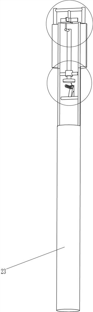
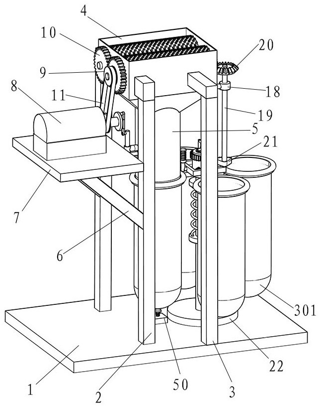
[0030] An automatic bagging device for blow molding waste crushing, see Figure 1-8 , including a bottom plate 1, a first bracket 2, a second bracket 3, a pulverizer 4, a lower barrel 5, a support block 6, a support plate 7, a motor 8, a transmission wheel 9, a first gear 10, a first belt 11, Pressing assembly, base 22, hollow pipe 23, fixed ring 24, rotating assembly, clamping assembly and first spring 26, the first bracket 2 and the second bracket 3 are all connected by bolts on the front and rear sides of the bottom plate 1 top, the first The bracket 2 is located on the left side of the second bracket 3, the upper part between the first bracket 2 and the second bracket 3 is installed with a pulverizer 4 through bolts, the bottom of the pulverizer 4 is connected with the lower barrel 5, and the left middle of the two first brackets 2 Both support blocks 6 are connected, and the support blocks 6 are inclined. The tops of the two support blocks 6 are connected with a support p...

Embodiment 2

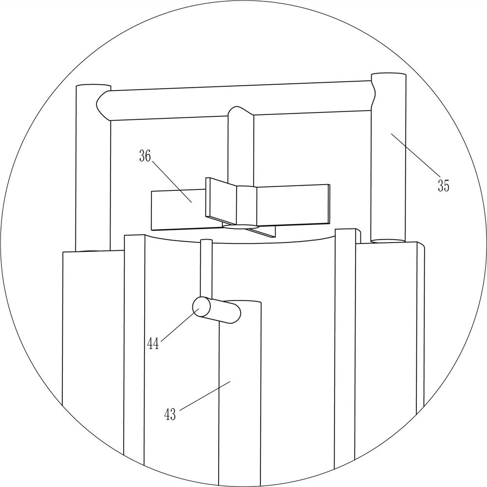
[0039] On the basis of Example 1, see figure 1 , Figure 4 , Figure 9 , Figure 10 and Figure 11 , also includes metal ball 32, telescoping rod 31, second spring 33, fourth guide sleeve 45, slide bar 46, block 47, fourth spring 48 and rectangular frame 49, and the outside of sliding sleeve 28 is embedded with two A telescopic rod 31, a metal ball 32 is connected to the outer end of the telescopic rod 31, a second spring 33 is connected between the metal ball 32 and the sliding sleeve 28, the second spring 33 is wound on the telescopic rod 31, and the lower part of the lower right side of the lower barrel 5 is connected to A fourth guide sleeve 45 is arranged, and a slide bar 46 is slidably provided in the fourth guide sleeve 45. The top end of the slide bar 46 is connected with a stopper 47, and a fourth spring 48 is connected between the stopper 47 and the fourth guide sleeve 45. Four springs 48 are wound on the slide bar 46, and the right end of the slide bar 46 is con...


PUM


Abstract

The invention relates to an automatic bagging device, in particular to an automatic bagging device for blow molding waste crushing. The technical problem to be solved is to provide an automatic bagging device for crushing blow molded parts waste that does not require people to hold the bag all the time, can easily change the bag, and can save manpower and time. An automatic bagging device for blow molding waste crushing, including a bottom plate, a first bracket, a second bracket, etc.; both sides of the top of the bottom plate are fixedly connected with the first bracket and the second bracket. The present invention can press down the bag full of waste materials through the pressing assembly, and the rotating assembly can remove the bag full of waste materials and replace it with a new bag at the same time, so that people do not need to hold the bag for filling, thus saving manpower and labor. time, and the bag can be easily changed without spreading the waste all over the place; through the setting of the bell, it can remind people when the waste is full.

Description

technical field [0001] The invention relates to an automatic bagging device, in particular to an automatic bagging device for blow molding waste crushing. Background technique [0002] Blow molding, also known as hollow blow molding, is a rapidly developing plastic processing method. During the blow molding process, there must be wear and tear. Before starting the machine or when adjusting the width and thickness of plastic products, there will be scraps and unformed waste films. , within a certain period of time, it will accumulate a lot to cause wear and tear, which will increase the cost. Many businesses will directly crush it, add it to new particles for stirring, and use it again. The performance and characteristics will not change. It belongs to a kind of particle regeneration. . [0003] When people collect the crushed waste in bags, they need to manually open the mouth of the bag and align the mouth of the bag with the discharge port of the shredder. People need to ...

Claims


Application Information

Patent Timeline
Patent Type & Authority Patents(China)
IPC IPC(8): B65B43/50B65B57/18B65B1/04
CPCB65B1/04B65B43/50B65B57/18
Inventor 李付新
Owner 义乌市丹航科技有限公司
Why Eureka
Try Eureka