Bearing driving device used for vehicle sliding plug door

A driving device and vehicle technology, which is applied in the field of rail transit, can solve the problems of difficult installation and debugging, long mechanism length, and large space occupation, and achieve the effects of eliminating height difference, reducing instantaneous resistance, and occupying small space

Active Publication Date: 2020-06-19
NINGBO CRRC TIMES TRANSDUCER TECH CO LTD
View PDF11 Cites 3 Cited by
  • Summary
  • Abstract
  • Description
  • Claims
  • Application Information

AI Technical Summary

Problems solved by technology

[0003] The sliding door mechanism is widely used in the vehicle door system of urban rail vehicles and public transport vehicles. Most of the sliding door mechanisms at home and abroad are mainly divided into the following three types: the first one is to realize the switch in the direction of the X axis with the optical axis as the guide Door, the Y-axis direction realizes the plug-and-pull action, but it takes up a lot of space and has low synchronization; the second type uses the optical axis as the guide to realize the opening and closing of the door in the X-axis direction, and the Y-axis direction realizes the plug-and-pull action through the swing rod mechanism However, the length of the mechanism is long, there is a height difference in the process of opening and closing the door, and the resistance is relatively large at the moment of opening and closing the door; the third type is guided by a linear guide rail to realize the opening and closing of the door and the plug in the X-axis and Y-axis directions. However, its own mechanism is complicated, and it is difficult to install and debug

Method used


Image

  • Bearing driving device used for vehicle sliding plug door
  • Bearing driving device used for vehicle sliding plug door
  • Bearing driving device used for vehicle sliding plug door

Examples


Embodiment Construction

[0034] The following are specific embodiments of the present invention and in conjunction with the accompanying drawings, the technical solutions of the present invention are further described, but the present invention is not limited to these embodiments.

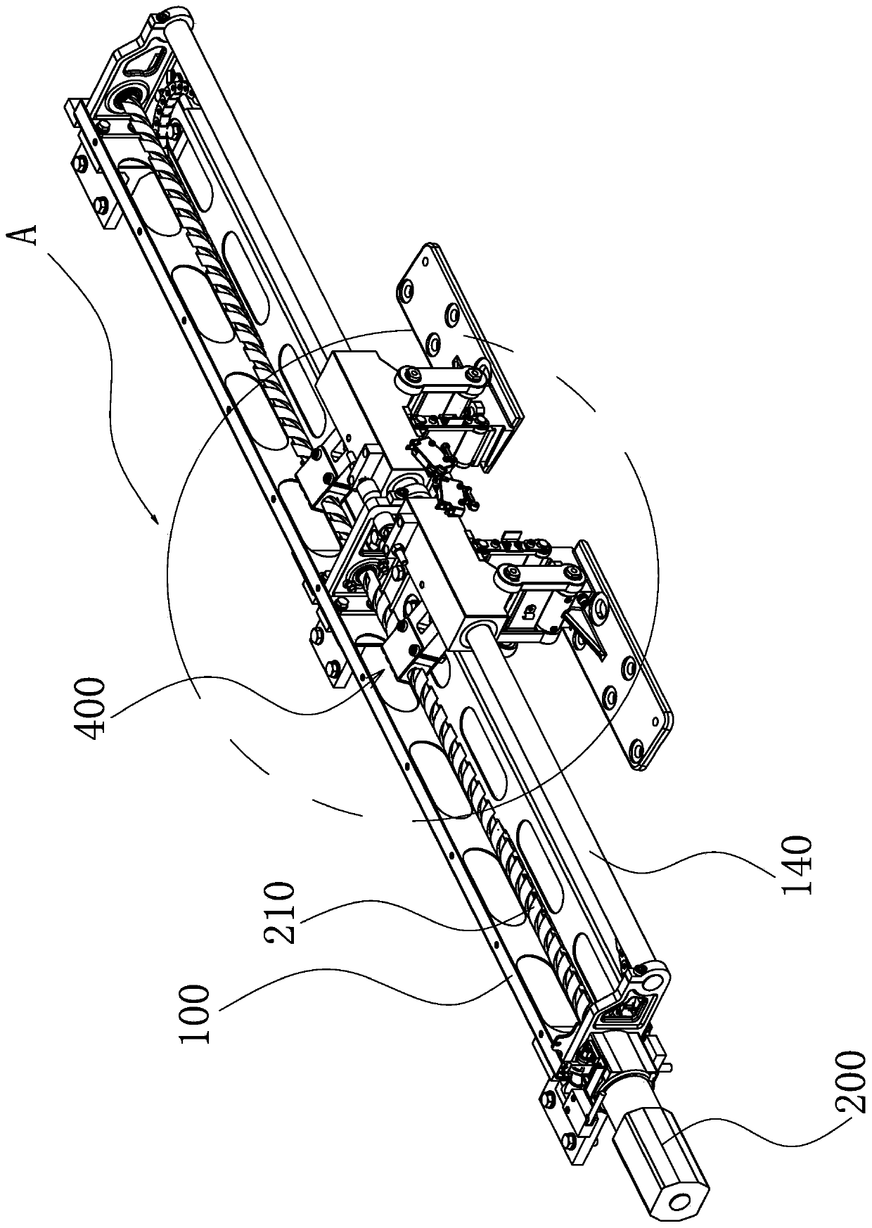
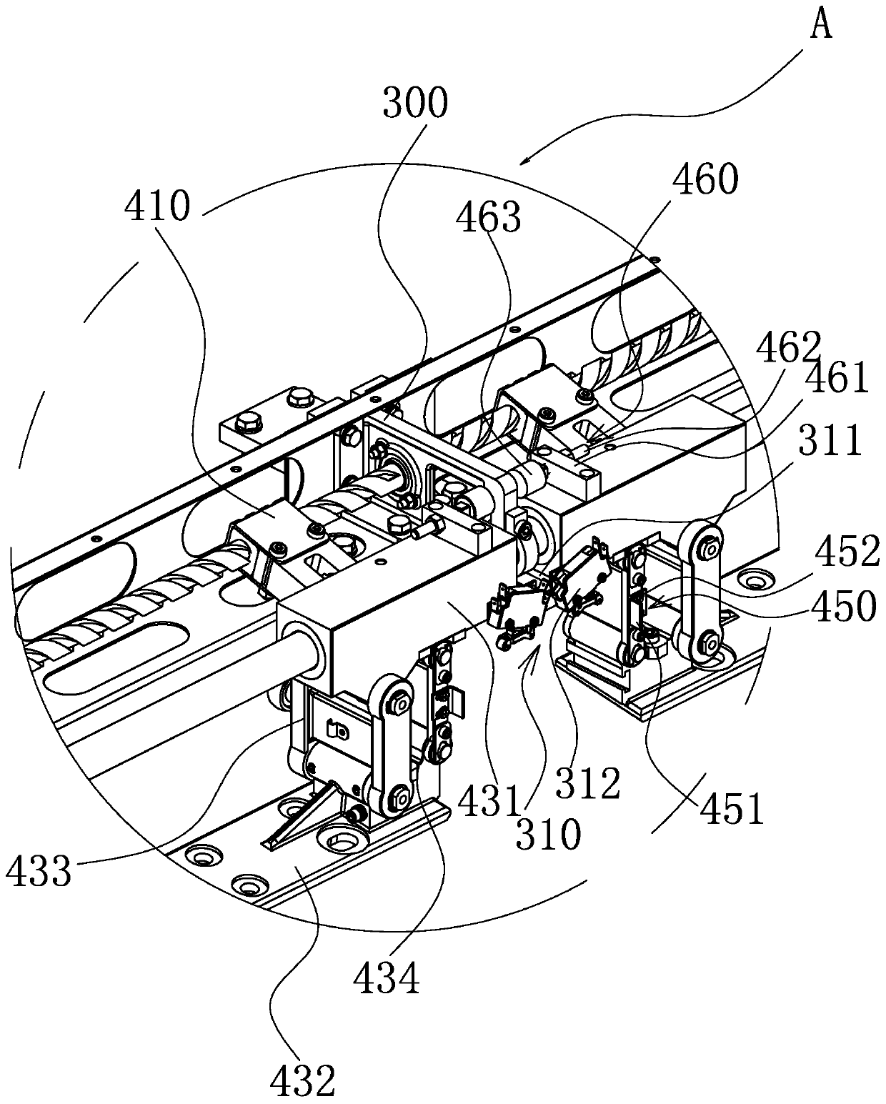
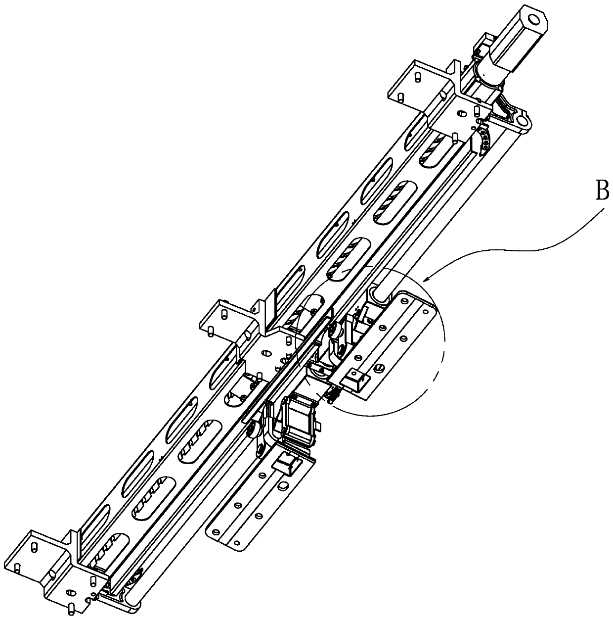
[0035] like Figure 1 to Figure 5 As shown, a load-carrying drive device for a vehicle sliding door provided by the present invention includes: a frame 100 as a carrier, wherein two first triggering parts 110 are arranged on the frame 100; a motor 200 is installed At one end of the frame 100, wherein the output end of the motor 200 is connected to a transmission part 210; the hanger 300 is located between the two first trigger parts 110, wherein one end of the hanger 300 is installed on the frame 100, The other end of the hanger 300 is equipped with two symmetrical second trigger parts 310; two transmission mechanisms 400 are respectively located on both sides of the hanger 300, and one end of each transmission mechanism 4...


PUM


Abstract

The invention provides a bearing driving device used for a vehicle sliding plug door and belongs to the technical field of rail traffic. The bearing driving device comprises a rack, a motor, a hangingrack and two transmission mechanisms, wherein the motor is mounted at one end of the rack; the output end of the motor is connected with a transmission part; the hanging rack is mounted on the middleportion of the rack, and the transmission part penetrates through the hanging rack; the two transmission mechanisms are located on the two sides of the hanging racks correspondingly; one end of eachtransmission mechanism is in screwed connection with the transmission part, and the other end of each transmission mechanism is connected with a door leaf; each transmission mechanism comprises a four-bar linkage assembly and realizes horizontal sliding and plug sliding of the door leaf through stretching and retracting of the four-bar linkage assembly. The bearing driving device used for the vehicle sliding plug door, provided by the invention, realizes opening, closing and plug sliding of the door leaf of a vehicle through the four-bar linkage assemblies and is simple in structure and convenient to install and debug. Moreover, the problem of the height difference existing in the plug sliding process of an original door leaf due to a swinging mechanism is eliminated. The occupied space ofthe whole bearing driving device is small.

Description

technical field [0001] The invention belongs to the technical field of rail transit, and relates to a driving device, in particular to a bearing driving device for a sliding door of a vehicle. Background technique [0002] With the development of urban rail and bus door systems, there are higher requirements for the functionality and reliability of the sliding door mechanism. As a key component, the sliding door mechanism is directly related to the operation function of the door system. [0003] The sliding door mechanism is widely used in the vehicle door system of urban rail vehicles and public transport vehicles. Most of the sliding door mechanisms at home and abroad are mainly divided into the following three types: the first one is to realize the switch in the direction of the X axis with the optical axis as the guide Door, the Y-axis direction realizes the plug-and-pull action, but it takes up a lot of space and has low synchronization; the second type uses the optical...

Claims


Application Information

Patent Timeline
Patent Type & Authority Applications(China)
IPC IPC(8): E05F15/655E05F15/652E05F17/00E05D15/10
CPCE05D15/1005E05D15/1044E05F17/004E05F2017/005E05Y2900/51E05Y2900/531E05F15/652E05F15/655
Inventor 段东梅彭毅黄兵王宝星华聪立沈敏杰
Owner NINGBO CRRC TIMES TRANSDUCER TECH CO LTD
Why Eureka
Try Eureka