Pipe setback

A technology of stand box and assembly, applied in the direction of drill pipe, casing, drill pipe, etc., can solve problems such as hidden danger of drilling stand pipe arrangement work, no buffer device in stand box, side slip of drill pipe stand, etc., so as to reduce the cleaning cost. and maintenance costs, easy disassembly, cleaning and maintenance, and the effect of improving safety

Pending Publication Date: 2020-06-19
SANY GRP
View PDF1 Cites 1 Cited by
  • Summary
  • Abstract
  • Description
  • Claims
  • Application Information

AI Technical Summary

Problems solved by technology

For the existing drilling floor manipulator technology, the traditional stand box's "flat" stand box cannot play the role of guiding the drill pipe stand and assisting the stand positioning when the manipulator arranges the pipe.
And for low-temperature freezing weather, the rubber pad laid on the table has no fixing device, which may easily cause the rubber pad to slip or the drill pipe stand to slide sideways, which will bring safety hazards to the drilling stand pipe arrangement work
[0003] In the prior art, the utility model patent CN208619065U provides a new type of metal stand box, but the stand box will cause the stand box to have no buffer device, and the drill pipe and the stand box will be in contact with "steel against steel" when the pipe is arranged, which is very easy to cause drilling. Damaged rod thread
The large round tubes and the small round tubes are arranged tangentially in pairs. If the assembly type is placed directly, there is no fixing device, and the gap between the two tangent round tubes rolls to cause the gap to be indeterminate.
If it is fixed by welding, the welding of the round pipe will easily cause the overall welding deformation, and the mud in the gap of the round pipe is difficult to clean

Method used


Image

  • Pipe setback
  • Pipe setback
  • Pipe setback

Examples


Embodiment Construction

[0029] In order to make the purposes, technical solutions and advantages of the embodiments of the present invention clearer, the technical solutions in the embodiments of the present invention will be clearly and completely described below with reference to the accompanying drawings in the embodiments of the present invention. Obviously, the described embodiments These are some embodiments of the present invention, but not all embodiments. The components of the embodiments of the invention generally described and illustrated in the drawings herein may be arranged and designed in a variety of different configurations.

[0030] Thus, the following detailed description of the embodiments of the invention provided in the accompanying drawings is not intended to limit the scope of the invention as claimed, but is merely representative of selected embodiments of the invention. Based on the embodiments of the present invention, all other embodiments obtained by those of ordinary ski...


PUM


Abstract

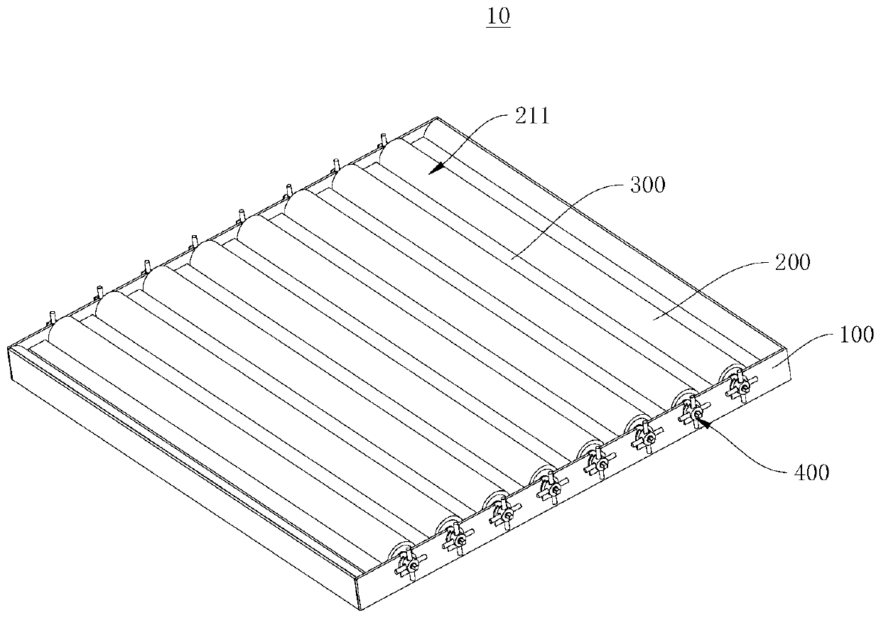
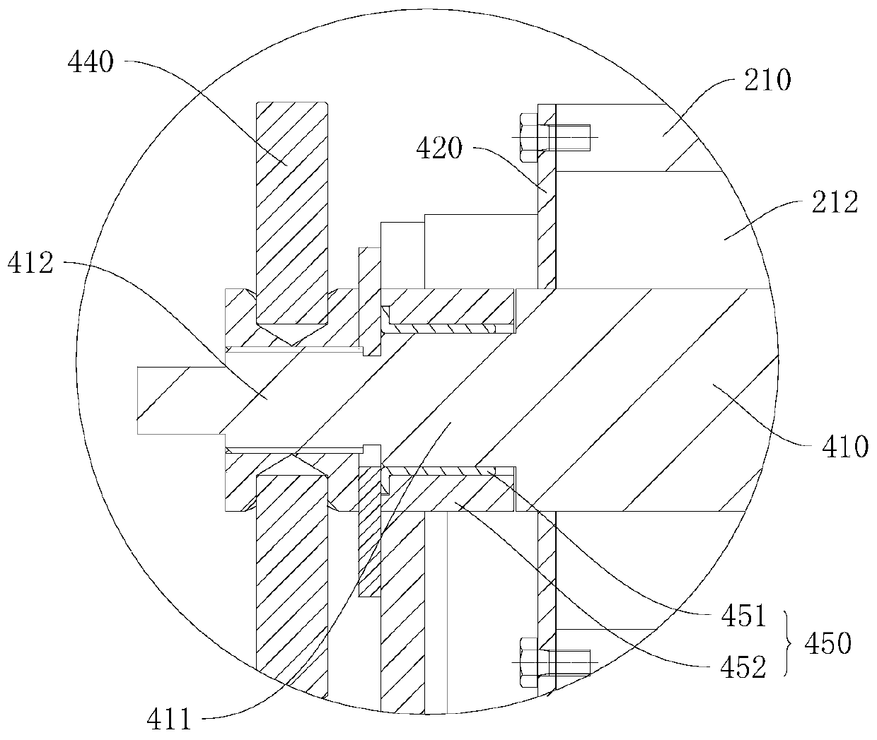
The invention provides a pipe setback, and relates to the technical field of oil field drilling machine equipment. The pipe setback is used for a drill rod three-joint unit and comprises a frame, a plurality of assembly type cross bar assemblies and a plurality of carbonized sleepers. The multiple assembly type cross bar assemblies are rotationally connected to the frame and detachably arranged relative to the frame, the multiple carbonized sleepers are detachably installed on the frame, the assembly type cross bar assemblies and the carbonized sleepers are arranged alternatively, the assemblytype cross bar assemblies form a guide arc face used for guiding a drill rod to the carbonized sleepers, and the carbonized sleepers are used for bearing the drill rod. The pipe setback provided by the invention can avoid direct steel-to-steel contact between the drill rod and the pipe setback, protects a screw threads of the drill rod, and is easy to clean, easy to maintain and simple in structure

Description

technical field [0001] The invention relates to the technical field of oil field drilling rig equipment, in particular to a stand box. Background technique [0002] In the oil industry, the stand boxes on the base platform of traditional drilling rigs are generally made of sleepers stacked into a rectangle, with rubber pads laid on them, and drill pipe stands are placed. For the existing manipulator technology for pipe arranging on the drilling floor, the traditional stand box cannot play the role of guiding the stand of the drill pipe and assisting the positioning of the stand when the manipulator arranges the pipe. In addition, in the low temperature freezing weather, the rubber pads laid on the table have no fixing device, which may easily cause the rubber pads to slip or the drill pipe stand to slide sideways, which will bring safety hazards to the drilling stand pipe arrangement. [0003] In the prior art, the utility model patent CN208619065U provides a new type of me...

Claims


Application Information

Patent Timeline
Patent Type & Authority Applications(China)
IPC IPC(8): E21B19/14
CPCE21B19/14
Inventor 唐清亮胡志勇傅炳炎
Owner SANY GRP
Why Eureka
Try Eureka