
Glass-fiber-reinforced-plastic axial flow fan

An axial flow fan, glass fiber reinforced plastic technology, applied in the direction of axial flow pump, mechanical equipment, machine/engine, etc., can solve the problems of noise pollution, affecting the use experience, mosquitoes flying around, to prevent the entry of mosquitoes and prevent fault damage , the effect of enhancing the experience effect

Active Publication Date: 2020-06-19
ZHEJIANG LINGGONG ELECTRIC APPLIANCE CO LTD
View PDF10 Cites 2 Cited by
  • Summary
  • Abstract
  • Description
  • Claims
  • Application Information

AI Technical Summary

Problems solved by technology

[0003] The air outlet of the traditional axial flow fan is open and open to the air. When the fan is working, there is no protective device at the air outlet, which may cause people to accidentally touch the fan blades that are running at high intensity. There is no noise isolation device for the entire fan. The sound generated at the time will cause noise pollution, and the airfoil of the blade surface of the ordinary fan blade is easy to deform after a long time of work, which will reduce the working efficiency of the fan and even cause damage to the equipment and cause danger; as the use time increases, mosquitoes are easy to enter the interior It sticks inside, causing the mosquitoes inside to remain, and when it is used again, the mosquitoes inside will be flushed out, causing the mosquitoes to fly randomly, thus affecting the user experience

Method used


Image

  • Glass-fiber-reinforced-plastic axial flow fan
  • Glass-fiber-reinforced-plastic axial flow fan
  • Glass-fiber-reinforced-plastic axial flow fan

Examples


Embodiment Construction

[0021] The following will clearly and completely describe the technical solutions in the embodiments of the present invention with reference to the accompanying drawings in the embodiments of the present invention. Obviously, the described embodiments are only some, not all, embodiments of the present invention. Based on the embodiments of the present invention, all other embodiments obtained by persons of ordinary skill in the art without making creative efforts belong to the protection scope of the present invention.

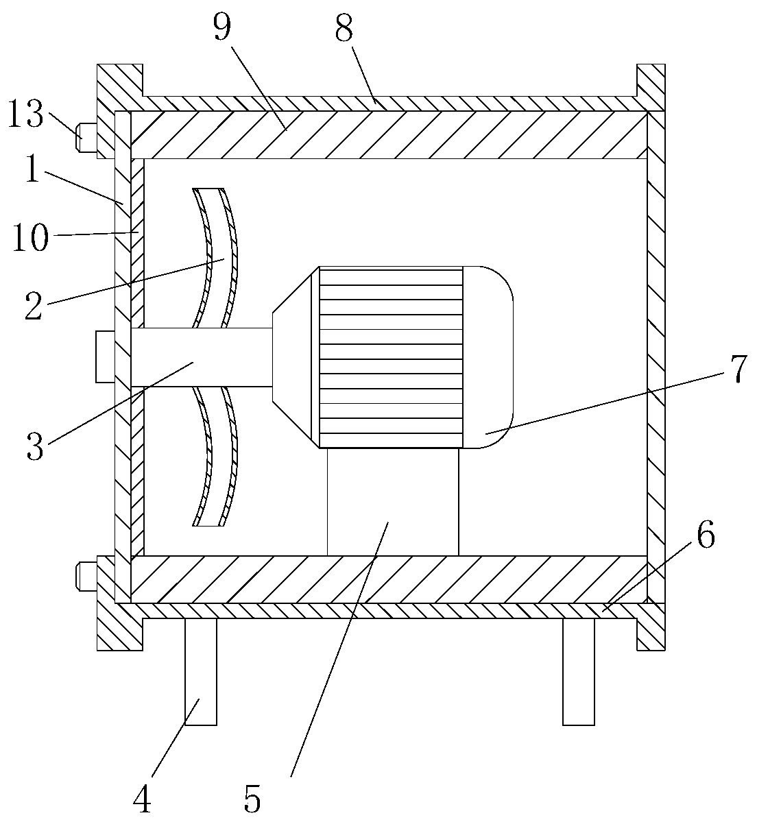
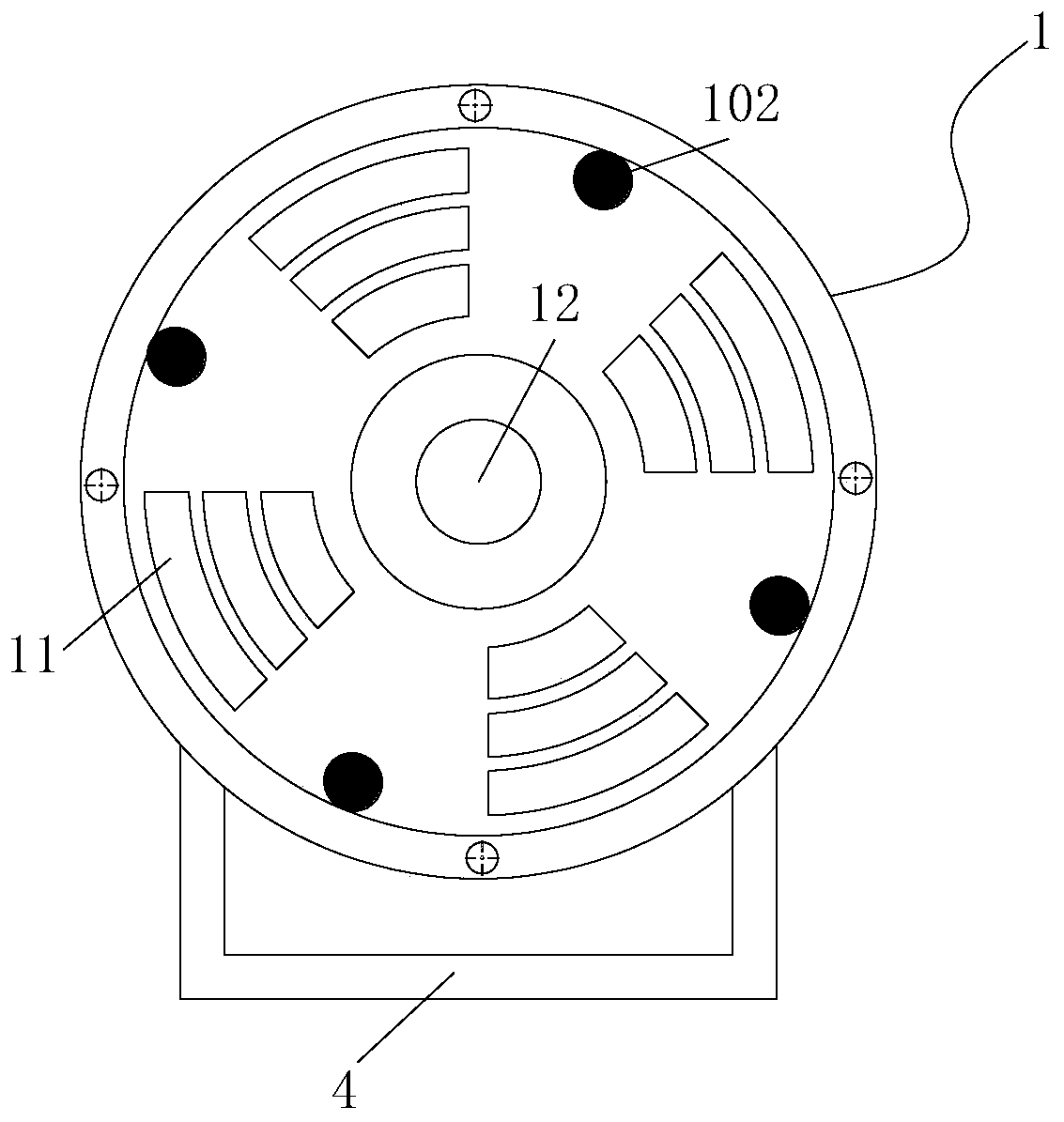
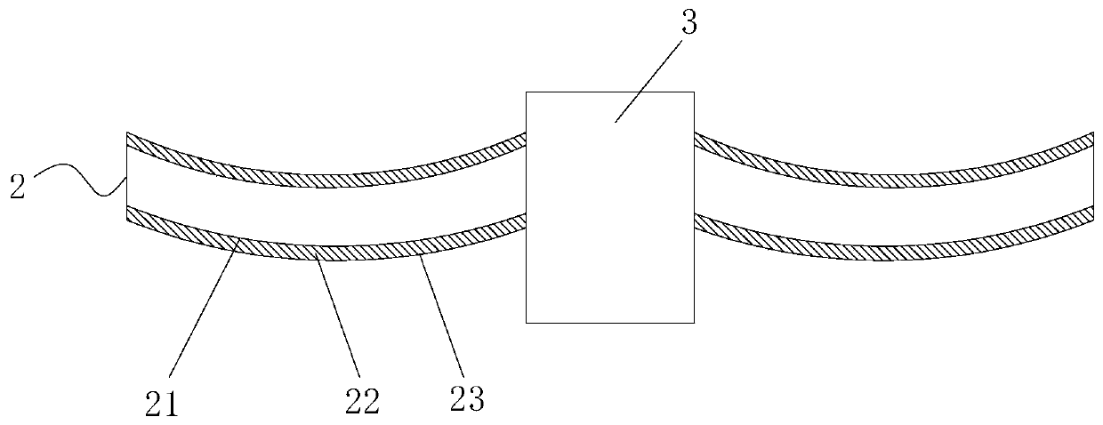
[0022] see Figure 1-4 , the present invention provides the following technical solutions: a fiberglass axial flow fan, comprising an air outlet protective cover 1, a fan impeller 2, a rotating shaft 3, a stand 4, a base 5, a fan lower casing 6 and a rotating motor 7, and a stand 4 Installed on the lower end of the fan lower casing 6, the top of the fan lower casing 6 is provided with a base 5, the rotating motor 7 is installed on the upper end of the base 5, ...


PUM


Abstract

The invention belongs to the technical field of axial flow fans, and particularly relates to a glass-fiber-reinforced-plastic axial flow fan. The axial flow fan comprises an air outlet protective cover, a fan impeller, a fan lower shell and a rotating motor, wherein a base is arranged above the fan lower shell, a rotating shaft is arranged on one side of the rotating motor, the air outlet protective cover is arranged on the side, away from the rotating motor, of the rotating shaft, and the fan impeller is arranged at the upper end of the rotating shaft. According to the axial flow fan, by installing the air outlet protective cover, it can be avoided that when the fan works, external personnel mistakenly touch the running fan impeller to cause ground injuries, a rotary button arranged on the air outlet protective cover can be connected with the rotating shaft to control rotation of an arc-shaped groove so as to further control the air direction and improve the working efficiency, soundabsorption cotton arranged in an upper shell and the lower shell of the fan can isolate noise generated when the fan works, and meanwhile, fan blades are provided with glass fiber reinforced plastic upper and lower layers and hollow inner cavities filled with polyurethane foam, and equipment failure damage caused by wing surface deformation after the blades work for a long time can be prevented.

Description

technical field [0001] The invention belongs to the technical field of axial flow fans, and in particular relates to a fiberglass axial flow fan. Background technique [0002] Axial flow fans have a wide range of uses, that is, the airflow in the same direction as the axis of the fan blades, such as electric fans and air conditioner external fans are axial flow fans. It is called "axial flow" because the gas flows parallel to the shaft of the fan. Axial flow fans are usually used in occasions with high flow requirements and low pressure requirements. Axial fans hold the position and move the air. The axial flow fan is mainly composed of the fan impeller and the casing. The structure is simple but the data requirements are very high. The ordinary axial flow fan can be used for ventilation in general factories, warehouses, offices, houses and other places. [0003] The air outlet of the traditional axial flow fan is open and open to the air. When the fan is working, there i...

Claims


Application Information

Patent Timeline
Patent Type & Authority Applications(China)
IPC IPC(8): F04D19/00F04D25/08F04D27/00F04D29/02F04D29/08F04D29/32F04D29/38F04D29/52F04D29/56F04D29/66F04D29/70
CPCF04D19/002F04D25/08F04D27/00F04D29/023F04D29/083F04D29/325F04D29/388F04D29/522F04D29/563F04D29/664F04D29/703
Inventor 杨忠寸杨子荣周超
Owner ZHEJIANG LINGGONG ELECTRIC APPLIANCE CO LTD
Learn More