
3d radar lens

A lens and radar technology, applied in the field of 3D radar lens, can solve problems such as incapacity, achieve the effect of strong ability to receive light, reduce step surfaces, and reduce tolerance sensitivity

Pending Publication Date: 2020-06-19
FOCTEK PHOTONICS LNC
View PDF0 Cites 3 Cited by
  • Summary
  • Abstract
  • Description
  • Claims
  • Application Information

AI Technical Summary

Problems solved by technology

[0003] 3D lidar lenses are used to receive light signals. The larger the aperture, the better the receiving performance. The existing 3d lidar lenses on the market usually have an aperture of 1.2 or more. For more and more complicated road conditions, lenses with an aperture of 1.2 appear to be more complex. We can’t do what we want, and it’s an urgent task to develop a lens with a large aperture

Method used


Image

  • 3d radar lens
  • 3d radar lens
  • 3d radar lens

Examples


Embodiment Construction

[0032] The present invention is described in detail below in conjunction with accompanying drawing description:

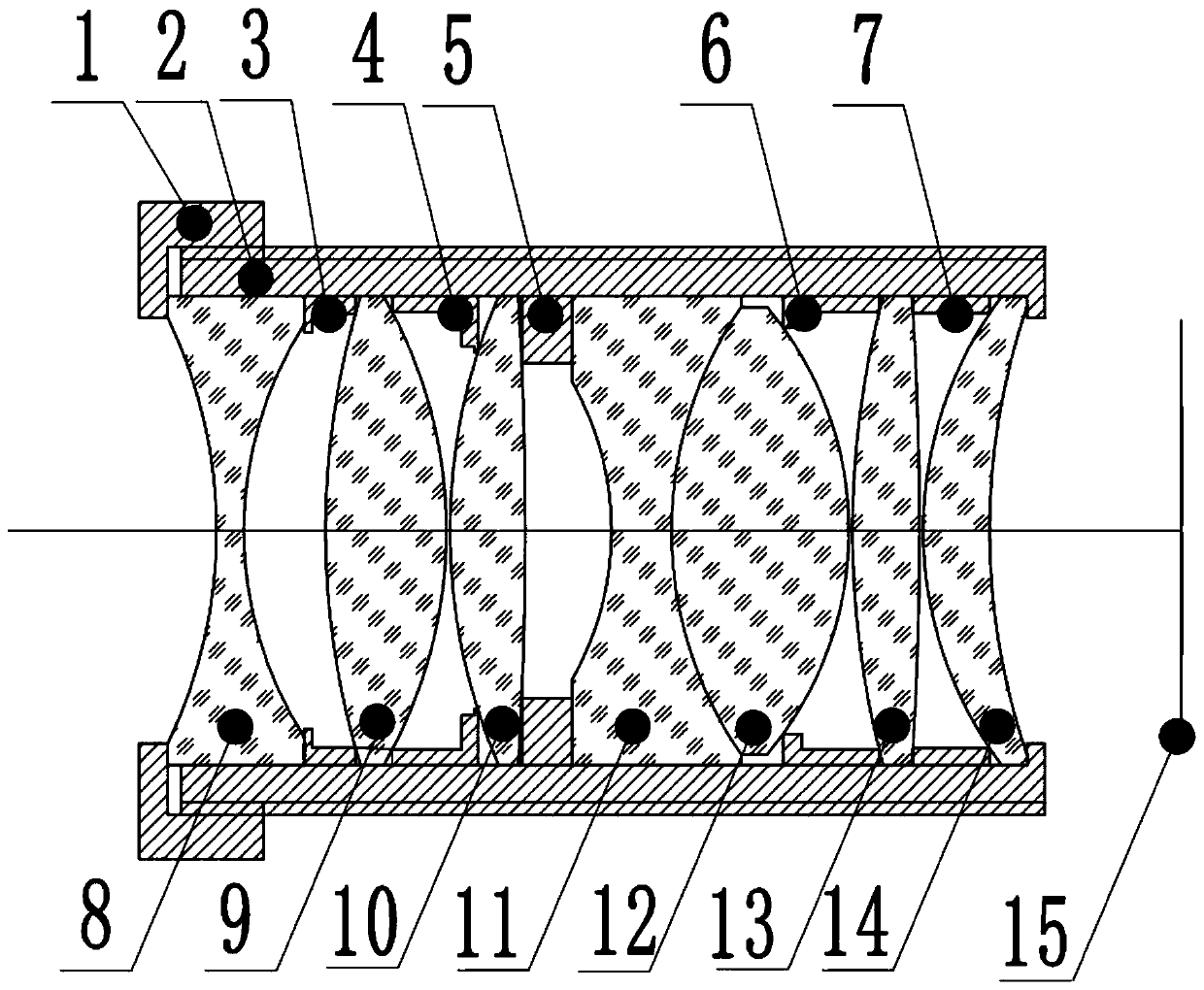
[0033] Such as figure 1 As shown, a 3D radar lens is characterized in that: it comprises a main lens barrel 2, a front lens group arranged in the main lens barrel 2 along the incident direction of light, a diaphragm, a rear lens group, and a front lens group arranged in the main lens barrel 2. The photosensitive chip 15 at the rear end, the optical power of the front mirror group is 8-20mm, and the optical power of the rear mirror group is 8.5-15mm;

[0034] The front lens group includes a first lens 8, a second lens 9 and a third lens 10 arranged in sequence along the light incident direction, and the rear lens group includes a fourth lens 11 and a fifth lens 12 arranged in sequence along the light incident direction , the sixth lens 13 and the seventh lens 14;

[0035] The first lens 8 is a biconcave lens, the second lens 9 is a biconvex lens, the third lens 10...


PUM


Abstract

The invention relates to a 3d radar lens. The3d radar lens comprises a main lens barrel, a front lens group, a diaphragm and a rear lens group sequentially arranged in the main lens barrel along the incident direction of light, and a photosensitive chip arranged at the rear end of the main lens barrel. The focal power of the front lens group is 8-20mm, and the focal power of the rear lens group is8.5-15mm; the front lens group comprises a first lens, a second lens and a third lens which are sequentially arranged along the incident direction of light, and the rear lens group comprises a fourthlens, a fifth lens, a sixth lens and a seventh lens which are sequentially arranged along the incident direction of light; the first lens is a biconcave lens, the second lens is a biconvex lens, thethird lens is a biconvex lens, the fourth lens is a biconcave lens, the fifth lens is a biconvex lens, the sixth lens is a biconvex lens, and the seventh lens is a meniscus lens. The invention provides the 3d radar lens of which the aperture can reach 0.8, the lens has strong light receiving capability, and the ranging distance of laser radar can be effectively improved.

Description

technical field [0001] The invention relates to the lens field, in particular to a 3D radar lens. Background technique [0002] The laser radar ranging technology obtains the three-dimensional information of the scene through laser scanning. The basic principle is to emit laser light into the space according to a certain time interval, and record the signal of each scanning point, and calculate the interval time from the laser radar to the object in the scene under test, and then reflect back to the laser radar through the object. The distance between the surface of the object and the lidar. Lidar is widely used in artificial intelligence systems for outdoor three-dimensional space perception due to its wide ranging range and high measurement accuracy, such as obstacle avoidance navigation for autonomous vehicles, 3D scene reconstruction and other applications. [0003] 3D lidar lenses are used to receive light signals. The larger the aperture, the better the receiving per...

Claims


Application Information

Patent Timeline
Patent Type & Authority Applications(China)
IPC IPC(8): G02B7/02G02B1/00G02B27/00G01S17/93G01S17/08G01S7/481G03B30/00
CPCG02B7/021G02B1/00G02B27/0025G01S17/08G01S7/4816
Inventor 黄统樑
Owner FOCTEK PHOTONICS LNC
Learn More