Optical design of large-caliber large-aperture ultra-long-focus low-light level imaging lens

An optical design and large-aperture technology applied in the lens field to achieve the effect of improving picture quality

Active Publication Date: 2020-06-19
中科天极(新疆)空天信息有限公司
5 Cites 1 Cited by

AI-Extracted Technical Summary

Problems solved by technology

[0002] At present, there is a lack of high-resolution low-light night vision lenses with u...

Method used

In this specific embodiment, the refractive index of the first eyeglass G1 is 1.568832, the refractive index of the second eyeglass G2 is 1.516797, the refractive index of the 3rd eyeglass G3 is 1.846666, the refractive index of the 4th eyeglass G4 is 1.568832, the first The refractive index...

Abstract

The invention discloses an optical design of a large-caliber large-aperture ultra-long-focus low-light level imaging lens. The lens comprises a main lens barrel, a first lens, a second lens, a third lens, a fourth lens, a fifth lens, a sixth lens and a seventh lens are sequentially arranged in the main lens barrel in the light incident direction, and the outer diameters of the lenses are sequentially decreased progressively. Parameters of the large-caliber ultra-long-focus low-light-level imaging lens are obtained through complex optical calculation and design, the focal length of the lens reaches 300 mm, and the lens can be matched with a 1-inch photosensitive chip. Practice proves that the low-light-level night vision imaging lens manufactured through the optical design is clear and sharp in effect, and meanwhile, the light transmittance of the lens is greatly improved, so that imaging equipment can shoot clear and bright images in an extremely weak environment, and the picture quality of dynamic and static monitoring at night is greatly improved.

Application Domain

Technology Topic

Lens effectTransmittance +6

Image

  • Optical design of large-caliber large-aperture ultra-long-focus low-light level imaging lens
  • Optical design of large-caliber large-aperture ultra-long-focus low-light level imaging lens
  • Optical design of large-caliber large-aperture ultra-long-focus low-light level imaging lens

Examples

  • Experimental program(1)

Example Embodiment

[0031] In the description of the present invention, it should be understood that the terms "center", "longitudinal", "transverse", "length", "width", "thickness", "upper", "lower", "front", " "Back", "Left", "Right", "Vertical", "Horizontal", "Top", "Bottom", "Inner", "Outer", "Clockwise", "Counterclockwise" and other directions or positions indicated The relationship is based on the orientation or positional relationship shown in the drawings, which is only for the convenience of describing the present invention and simplifying the description, rather than indicating or implying that the device or element referred to must have a specific orientation, be constructed and operated in a specific orientation, therefore It cannot be understood as a limitation to the present invention.
[0032] In the present invention, the terms "installed", "connected", "connected", "fixed", "socket" and other terms should be construed broadly, unless clearly stipulated and limited otherwise. For example, they may be connected or Removable connection, or integral connection; it can be mechanical connection or electrical connection; it can be directly connected or indirectly connected through an intermediate medium, and it can be the internal communication between two components. For those of ordinary skill in the art, the specific meanings of the above terms in the present invention can be understood according to specific circumstances.
[0033] The present invention will be further described below in conjunction with the drawings.
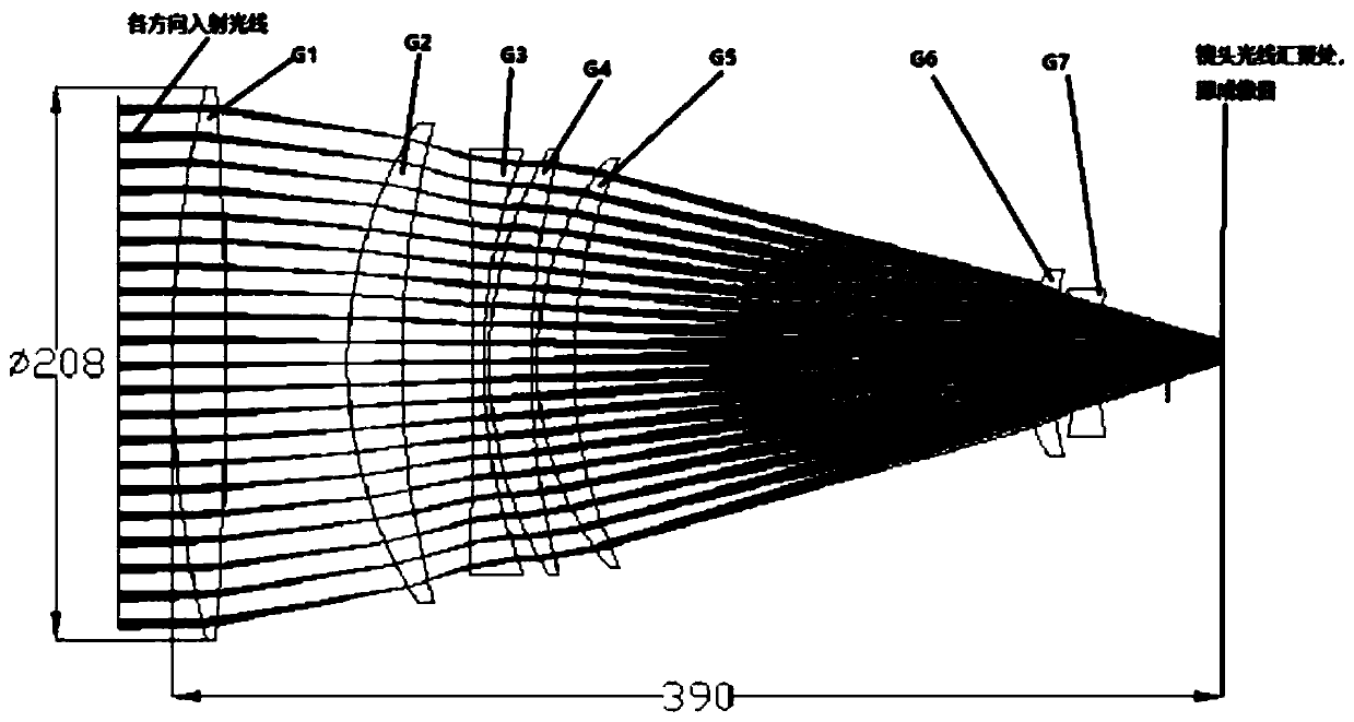
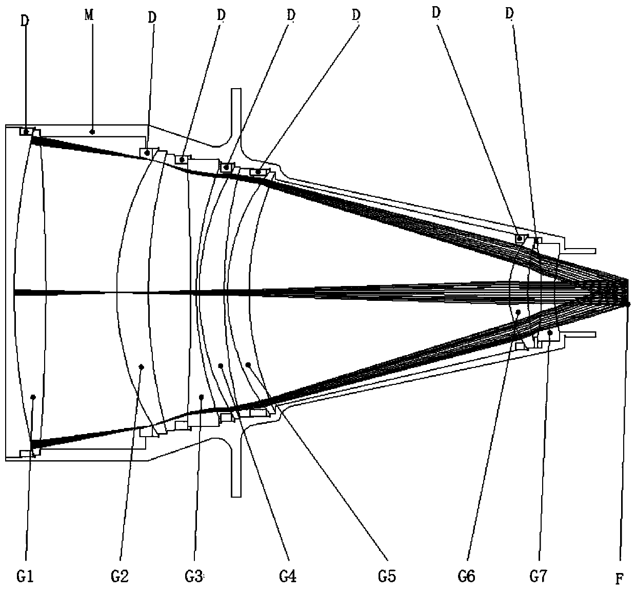
[0034] Such as Figure 1-2 As shown, the optical design of a large-aperture, large-aperture, ultra-telephoto, low-light imaging lens includes a main lens barrel M, and the main lens barrel M is sequentially provided with a first lens G1, a second lens G2, and a third lens along the light incident direction. G3, the fourth lens G4, the fifth lens G5, the sixth lens G6 and the seventh lens G7, and the outer diameter of the lens decreases in order;
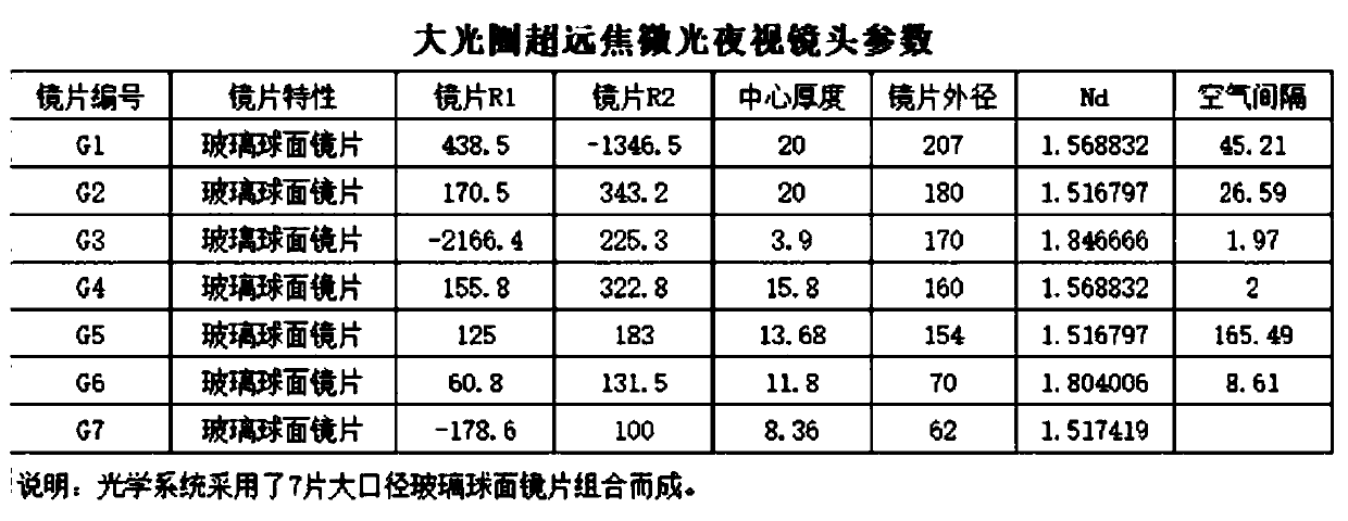
[0035] The outer surface of the first lens G1 is a circular arc convex surface, the radius of curvature of the circular arc convex surface is 438.5mm, the inner surface of the first lens G1 is a circular arc convex surface, the radius of curvature of the circular arc convex surface is -1346.5mm; the second lens The outer surface of G2 is an arc convex surface, the radius of curvature of the arc convex surface is 170.5mm, the inner surface of the second lens G2 is an arc concave surface, the radius of curvature of the arc concave surface is 343.2mm; the outer surface of the third lens G3 It is a circular arc concave surface, the radius of curvature of the circular arc concave surface is -2166.4mm, the inner surface of the third lens G3 is a circular arc concave surface, the radius of curvature of the circular arc concave surface is 225.3mm; the outer surface of the fourth lens G4 is a circular arc Convex surface, the radius of curvature of the arc convex surface is 155.8mm, the inner surface of the fourth lens G4 is an arc concave surface, the radius of curvature of the arc concave surface is 322.8mm; the outer surface of the fifth lens G5 is an arc convex surface, the circle The radius of curvature of the arc convex surface is 125mm, the inner surface of the fifth lens G5 is a circular arc concave surface, and the radius of curvature of the circular arc concave surface is 183mm; the outer surface of the sixth lens G6 is a circular arc convex surface, and the radius of curvature of the circular arc convex surface is 60.8mm, the inner surface of the sixth lens G6 is a circular arc concave surface, the radius of curvature of the circular arc concave surface is 131.5mm; the outer surface of the seventh lens G7 is a circular arc concave surface, and the radius of curvature of the circular arc concave surface is -178.6mm, The inner surface of the seventh lens G7 is a circular arc convex surface, the radius of curvature of the circular arc convex surface is 100mm; the air gap between the first lens G1 and the second lens G2 is 45.21mm, and the second lens G2 and the third lens G3 The air gap between the two lenses is 26.59mm, the air gap between the third lens G3 and the fourth lens G4 is 1.97mm, the air gap between the fourth lens G4 and the fifth lens G5 is 2mm, the fifth lens G5 and the sixth lens G5 The air interval between the lenses G6 is 165.49 mm, and the air interval between the sixth lens G6 and the seventh lens G7 is 8.61 mm. This lens is used as an ultra-telephoto low-light imaging lens. In practical applications, through the cooperation of the main lens barrel M and the focusing structure, the entire group of optical lenses are adjusted for the entire group of optical lenses to increase the clearance rate of the lens in low light conditions. An image is collected by setting a photosensitive element F on the back focus imaging surface of the lens.
[0036] In this specific embodiment, the first lens G1, the second lens G2, the third lens G3, the fourth lens G4, the fifth lens G5, the sixth lens G6, and the seventh lens G7 are respectively fixed to the main lens barrel by a lock ring D Inside M.
[0037] In this specific embodiment, the outer diameter of the first lens G1 is 207mm, the outer diameter of the second lens G2 is 180mm, the outer diameter of the third lens G3 is 170mm, and the outer diameter of the fourth lens G4 is 160mm. The outer diameter of the fifth lens G5 is 154 mm, the outer diameter of the sixth lens G6 is 70 mm, and the outer diameter of the seventh lens G7 is 62 mm.
[0038] In this specific embodiment, the center thickness of the first lens G1 is 20mm, the center thickness of the second lens G2 is 20mm, the center thickness of the third lens G3 is 3.9mm, the center thickness of the fourth lens G4 is 15.8mm, The center thickness of the lens G5 is 13.68 mm, the center thickness of the sixth lens G6 is 11.8 mm, and the center thickness of the seventh lens G7 is 8.36 mm.
[0039] In this embodiment, the refractive index of the first lens G1 is 1.568832, the refractive index of the second lens G2 is 1.516797, the refractive index of the third lens G3 is 1.846666, the refractive index of the fourth lens G4 is 1.568832, and the refractive index of the fifth lens G5 is 1.568832. The refractive index of is 1.516797, the refractive index of the sixth lens G6 is 1.804006, and the refractive index of the seventh lens G7 is 1.517419. The reasonable combination of lenses with different refractive indexes improves the collection of ambient light by this lens, which is beneficial to the improvement of image clarity.
[0040] In this embodiment, the first lens G1, the second lens G2, the third lens G3, the fourth lens G4, the fifth lens G5, the sixth lens G6, and the seventh lens G7 are all glass spherical lenses with the same material.
[0041] In this specific embodiment, the specific parameters of the optical lens are as image 3 As mentioned, the focal length of the optical lens in this embodiment is f=300mm, which can work at a working distance of more than 50m; aperture F/N0=1.5, optical back focus=23mm, and the distance between the outer surface of the first lens G1 and the imaging surface The center axis distance is 390mm. The photosensitive element F on the imaging surface can fit a one-inch photosensitive chip at most.
[0042] The performance test curve of this specific embodiment is as follows Figure 4-11 From the data of multiple tests of this lens, it can be clearly seen that the chief ray angle of the lens changes linearly, up to 2.4 degrees, the relative illuminance is greater than 99%, and the optical distortion is less than 0.1%. It can be seen from the analysis of the MTF and OTF performance graphs. The lens image capture resolution can reach 1080P, which can provide high-definition resolution images. The working wavelength of the present invention is 500-900nm, after different working wavelengths are input, the optical path is the same figure 1 Same stability and can achieve infrared confocal.
[0043] The lens of the present invention has a large aperture and a large amount of light, the low-light night vision imaging lens has a clear and sharp effect, so that the imaging device can shoot clear and bright images in extremely weak environments, and greatly improves the picture quality of dynamic and static monitoring at night
[0044] The above embodiments are only used to illustrate the present invention, but not to limit the present invention. Those of ordinary skill in the relevant technical field can make various changes and modifications without departing from the spirit and scope of the present invention. Therefore, all The equivalent technical solutions also belong to the scope of the present invention, and the patent protection scope of the present invention should be defined by the claims.

PUM

PropertyMeasurementUnit
Center thickness20.0mm
Center thickness3.9mm
Center thickness15.8mm
tensileMPa
Particle sizePa
strength10

Description & Claims & Application Information

We can also present the details of the Description, Claims and Application information to help users get a comprehensive understanding of the technical details of the patent, such as background art, summary of invention, brief description of drawings, description of embodiments, and other original content. On the other hand, users can also determine the specific scope of protection of the technology through the list of claims; as well as understand the changes in the life cycle of the technology with the presentation of the patent timeline. Login to view more.

Similar technology patents

Classification and recommendation of technical efficacy words

Why Eureka
Try Eureka