Lens system, imaging module and electronic device
A lens system and lens technology, applied in the field of optical imaging, can solve problems such as difficult long focal length or ultra-long focal length, and achieve the effects of improving imaging quality, correcting aberrations, and improving flexibility
- Summary
- Abstract
- Description
- Claims
- Application Information
AI Technical Summary
Problems solved by technology
Method used
Image

Examples
Embodiment 1
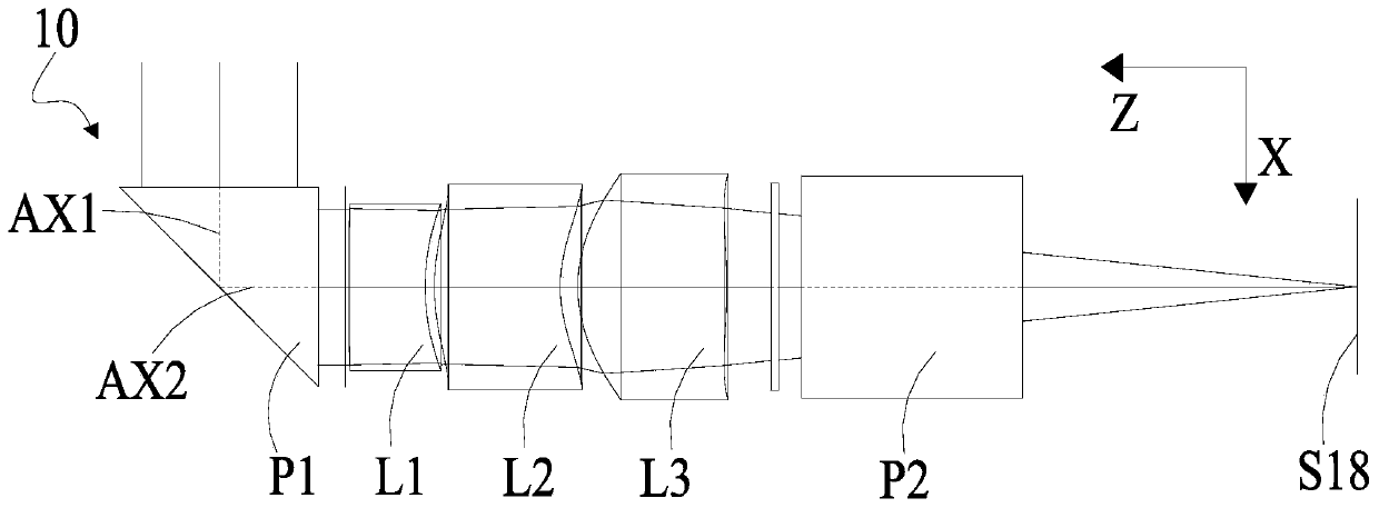
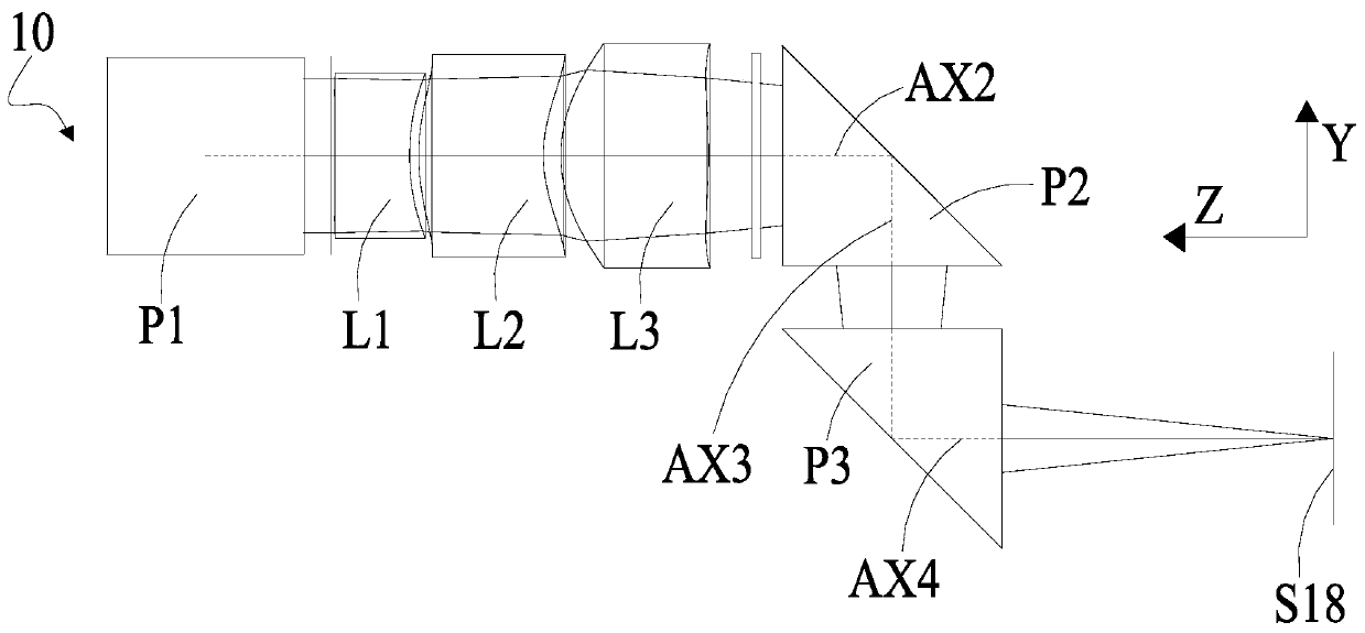
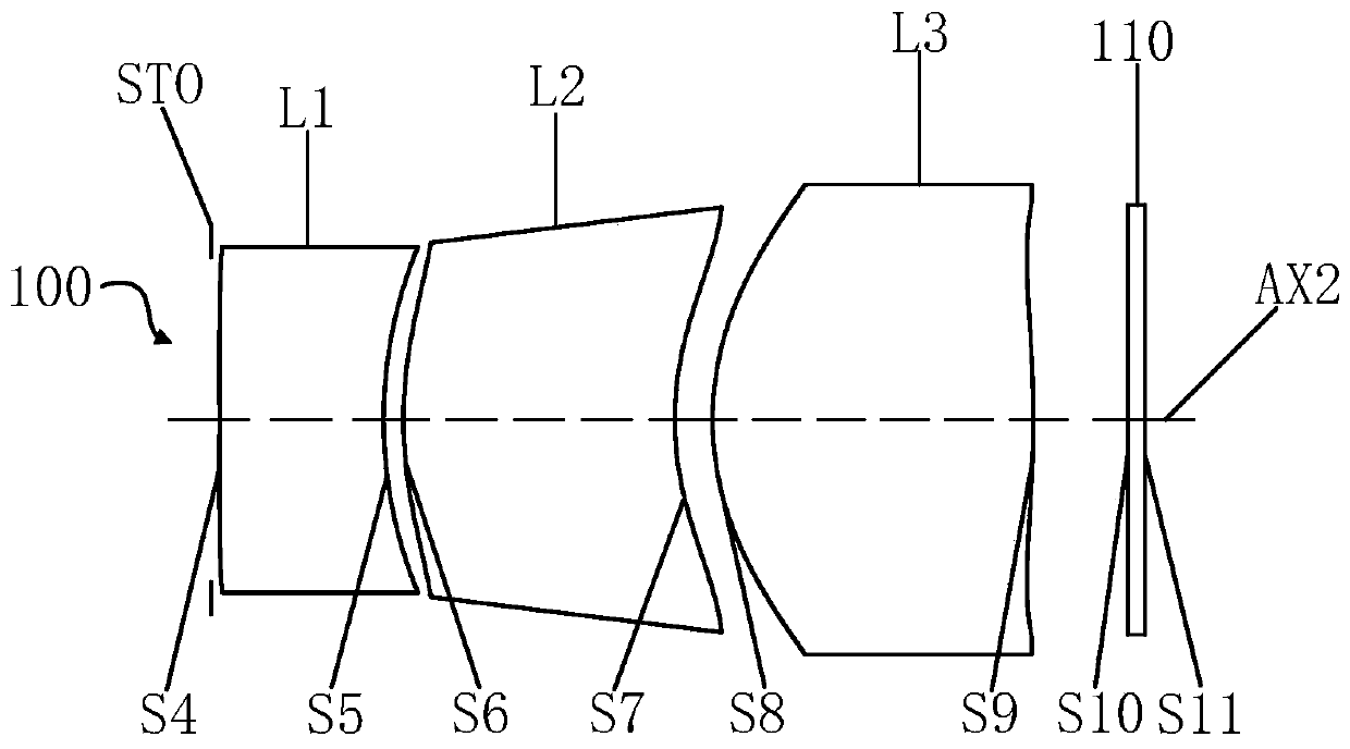
[0112] Refer to the following Figure 1 to Figure 4 The lens system 10 of Embodiment 1 of the present application will be described.
[0113] Such as Figure 1 to Figure 3 As shown, the lens system 10 sequentially includes a first right-angle prism P1, a first lens L1, a second lens L2, a third lens L3, a second right-angle prism P2, and a third right-angle prism from the object side to the image side along the folded optical axis. Prism P3 and imaging surface S18. The folded optical axis includes a first part AX1 , a second part AX2 , a third part AX3 and a fourth part AX4 , and the first lens L1 , the second lens L2 and the third lens L3 are located on the optical axis AX2 . further, figure 1 There is a Y-Z coordinate axis, figure 2 There are Y-X coordinate axes in it, wherein the optical axis AX1 is parallel to the X axis, the optical axis AX3 is parallel to the Y axis, and the optical axes AX2 and AX4 are parallel to the Z axis.
[0114] The first rectangular prism P...
Embodiment 2
[0140] Refer to the following Figure 5 to Figure 8 The lens system 10 of Embodiment 2 of the present application will be described. In this embodiment, for the sake of brevity, descriptions similar to those in Embodiment 1 will be omitted.
[0141] Such as Figure 5 to Figure 7 As shown, the lens system 10 sequentially includes a first right-angle prism P1, a first lens L1, a second lens L2, a third lens L3, a second right-angle prism P2, and a third right-angle prism from the object side to the image side along the optical axis. P3 and imaging surface S18. The folded optical axis includes a first part AX1 , a second part AX2 , a third part AX3 and a fourth part AX4 , and the first lens L1 , the second lens L2 and the third lens L3 are located on the optical axis AX2 .
[0142] The first rectangular prism P1 has a light incident surface S1 , a reflective surface S2 and a light output surface S3 .
[0143] The first lens L1 has a negative refractive power, and its object s...
Embodiment 3
[0157] Refer to the following Figure 9 to Figure 12 The lens system 10 of Embodiment 3 of the present application will be described. In this embodiment, for the sake of brevity, descriptions similar to those in Embodiment 1 will be omitted.
[0158] Such as Figure 9 to Figure 11 As shown, the lens system 10 sequentially includes a first right-angle prism P1, a first lens L1, a second lens L2, a third lens L3, a second right-angle prism P2, and a third right-angle prism from the object side to the image side along the optical axis. P3 and imaging surface S18. The folded optical axis includes a first part AX1 , a second part AX2 , a third part AX3 and a fourth part AX4 , and the first lens L1 , the second lens L2 and the third lens L3 are located on the optical axis AX2 .
[0159] The first rectangular prism P1 has a light incident surface S1 , a reflective surface S2 and a light output surface S3 .
[0160] The first lens L1 has a positive refractive power, and its object...
PUM
 Abstract
Description
Claims
Application Information
 - Generate Ideas
- Intellectual Property
- Life Sciences
- Materials
- Tech Scout
- Unparalleled Data Quality
- Higher Quality Content
- 60% Fewer Hallucinations
Browse by: Latest US Patents, China's latest patents, Technical Efficacy Thesaurus, Application Domain, Technology Topic, Popular Technical Reports.
© 2025 PatSnap. All rights reserved.Legal|Privacy policy|Modern Slavery Act Transparency Statement|Sitemap|About US| Contact US: help@patsnap.com