Check patentability & draft patents in minutes with Patsnap Eureka AI!

Circuit for controlling bias current

A bias current and current technology, applied in static memory, instruments, etc., can solve the problems of increasing IVCC current, affecting the life of the charge pump system, and high power supply noise.

Active Publication Date: 2020-06-19
GIGADEVICE SEMICON (BEIJING) INC +1
View PDF7 Cites 0 Cited by
  • Summary
  • Abstract
  • Description
  • Claims
  • Application Information

AI Technical Summary

Problems solved by technology

[0004] The current drive capability of the existing charge pump increases with the increase of the power supply voltage. When the settling time of the charge pump output voltage meets the requirements at the lower power supply voltage VCC, the establishment is too fast at the higher power supply voltage VCC, and due to the bias The current is basically unchanged, so that the frequency of the clock signal generated by the clock circuit is basically unchanged. The charge pump system needs to get more current from the power supply voltage VCC to ensure the current driving capability of the charge pump, resulting in a high peak current of VCC. , the higher peak current will affect the service life of the charge pump system, and also affect the performance of other circuits in the system, and the power supply noise will be relatively large, refer to figure 2 , shows the peak current of the charge pump system under different power supply voltages in the prior art, where VCC refers to the power supply voltage, IVCC refers to the peak current on VCC, and when VCC=1.5V, IVCC is about 17.5 mA , when VCC=2.0V, IVCC is about 27 mA, and when VCC=2.4V, IVCC is about 34 mA. It can be seen that with the increase of VCC, the current of IVCC increases rapidly

Method used


Image

  • Circuit for controlling bias current
  • Circuit for controlling bias current
  • Circuit for controlling bias current

Examples


Embodiment Construction

[0065] In order to make the above objects, features and advantages of the present invention more comprehensible, the present invention will be further described in detail below in conjunction with the accompanying drawings and specific embodiments. It should be understood that the specific embodiments described here are only used to explain the present invention, only a part of the embodiments of the present invention, not all the embodiments, and are not intended to limit the present invention.

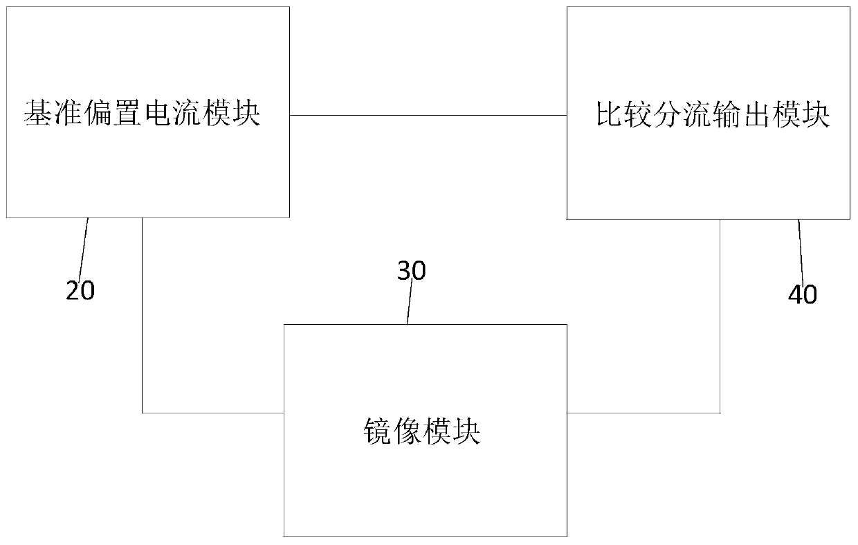
[0066] refer to image 3 , which shows a schematic diagram of the module for controlling the bias current circuit, which may specifically include:

[0067] The reference bias current module 20 , the mirror module 30 and the comparison shunt output module 40 .

[0068] The reference bias current module 20 is connected with the mirror image module 30 and the comparison shunt output module 40 respectively, and is used to generate the reference bias current. The bias current is mirrore...


PUM


Abstract

The invention discloses a circuit for controlling bias current. The circuit includes: a circuit board; a reference bias current module, a mirror image module and a comparison shunt output module; thereference bias current module is connected with the mirror image module and the comparison shunt output module. The bias circuit is used for generating reference bias current; the mirror image moduleis connected with the reference bias current module and the comparison shunt output module. The comparison shunt output module is used for mirroring the reference bias current to generate a first mirroring current and a fixed bias current, and the comparison shunt output module is connected with the reference bias current module and the mirroring module and used for generating a clock mirroring current based on the first mirroring current and the fixed bias current. According to the circuit provided by the invention, when the power supply voltage of the nonvolatile memory rises, the bias current is reduced, the current capability of the charge pump is reduced, and the peak current on the power supply voltage during VOUT establishment is reduced.

Description

technical field [0001] The invention relates to the field of nonvolatile memory, in particular to a circuit for controlling bias current. Background technique [0002] At present, the charge pump system in the non-volatile memory basically provides the non-volatile memory with the working voltage that meets the working requirements. The charge pump system includes a bias circuit, a clock circuit and a charge pump body. The current is mirrored to the clock circuit, and the clock circuit generates a clock signal to the main body of the charge pump, and the charge pump outputs a voltage according to the clock signal. [0003] The bias circuit in the charge pump system of the existing non-volatile memory is as shown in the accompanying drawings of the specification figure 1 , its working principle is: when the charge pump system is not working, according to the principle of MOS transistors, the power supply voltage VCC makes the first PMOS transistor 10 conduct, the reference v...

Claims


Application Information

Patent Timeline
IPC IPC(8): G11C5/14
CPCG11C5/146
Inventor 张现聚欧健胡俊
Owner GIGADEVICE SEMICON (BEIJING) INC
Features
  • R&D
  • Intellectual Property
  • Life Sciences
  • Materials
  • Tech Scout
  • Unparalleled Data Quality
  • Higher Quality Content
  • 60% Fewer Hallucinations
Learn More