
Switch structure

A switch structure and component technology, which is applied in the parts of flip switches/rocker switches, etc., can solve problems such as poor user experience

Pending Publication Date: 2020-06-19
TCL INT ELECTRICAL HUIZHOU
View PDF0 Cites 0 Cited by
  • Summary
  • Abstract
  • Description
  • Claims
  • Application Information

AI Technical Summary

Problems solved by technology

[0004] Based on this, it is necessary to provide a switch structure for the problem of poor user experience of the switch structure

Method used


Image

  • Switch structure
  • Switch structure
  • Switch structure

Examples


Embodiment Construction

[0037] In order to facilitate the understanding of the present application, the switch structure will be described more fully below with reference to the relevant drawings. A preferred embodiment of the switch structure is given in the accompanying drawings. However, the switch structure can be implemented in many different forms and is not limited to the embodiments described herein. On the contrary, the purpose of providing these embodiments is to make the disclosure of the switch structure more thorough and comprehensive.

[0038] It should be noted that when an element is referred to as being “fixed” to another element, it can be directly on the other element or there can also be an intervening element. When an element is referred to as being "connected to" another element, it can be directly connected to the other element or intervening elements may also be present. The terms "vertical," "horizontal," "left," "right," and similar expressions are used herein for purposes...


PUM


Abstract

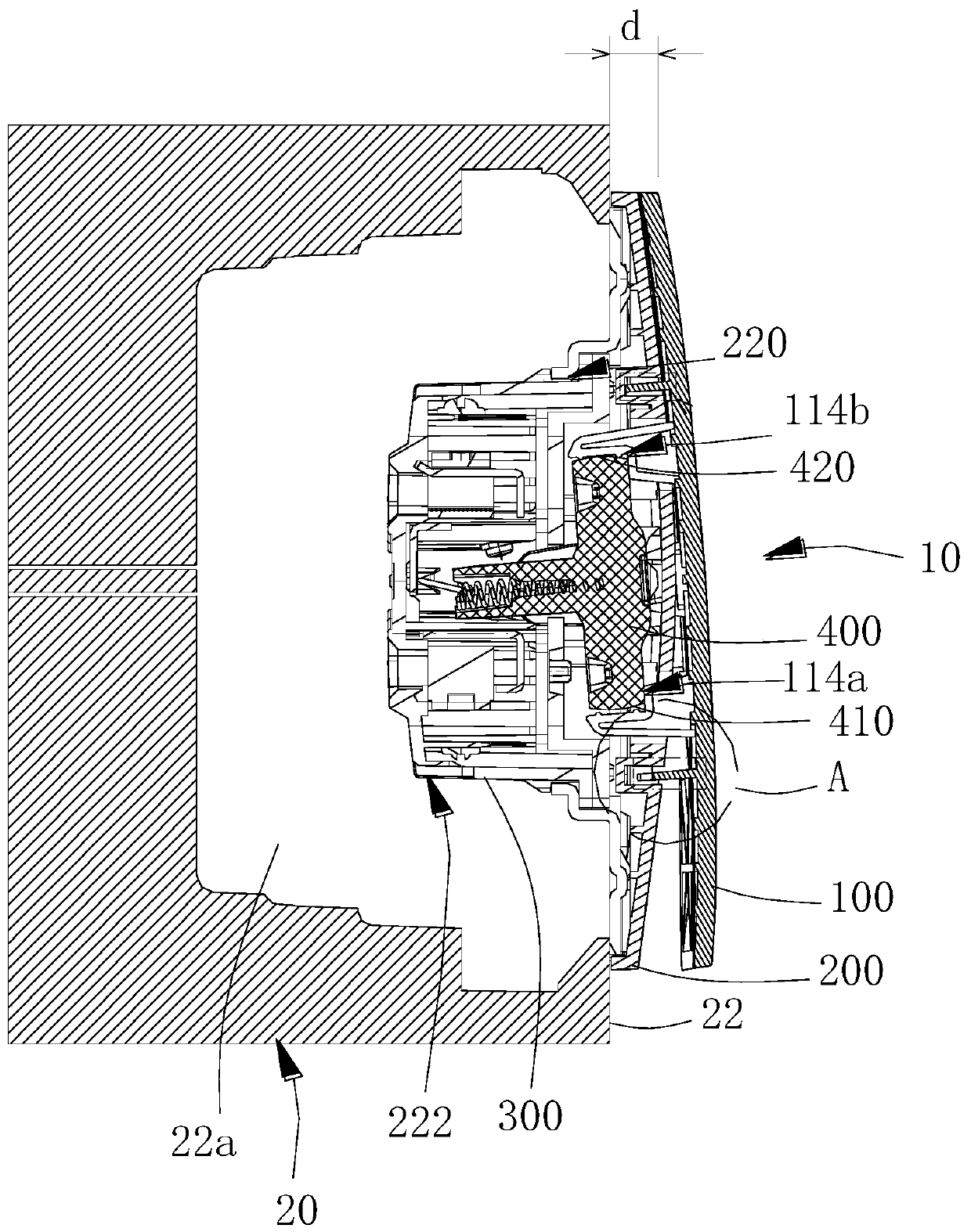
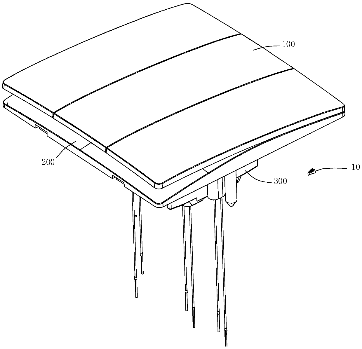
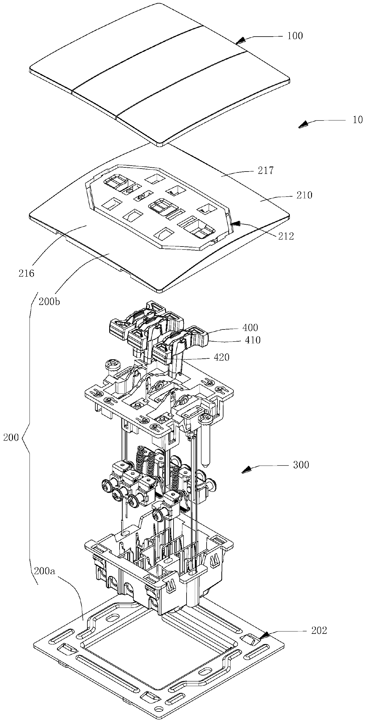
The invention relates to a switch structure. The switch structure comprises a key and a support plate assembly. One surface, adjacent to the support plate assembly, of the key is a first curved surface, and the first curved surface comprises a first binding surface, a connecting surface and a second binding surface; the connecting surface is connected with the first binding surface and the secondbinding surface respectively, and the connecting surface is provided with a convex pivoting piece; the surface, close to the key, of the support plate assembly is a second curved surface; the second curved surface is provided with a first mounting hole; the pivoting piece penetrates through the first mounting hole and is rotatably connected with the support plate assembly; the projection of the first binding surface on the second curved surface is a first projection surface; and the projection of the second binding surface on the second curved surface is a second projection surface. Compared with a traditional mode that the edge of the key makes contact with the support plate assembly, the switch structure provided by the invention has the advantages that the rotating attachment area of the key relative to the support plate assembly is large, vibration of the key of the switch structure during switch switching is greatly reduced, and the user experience degree of the switch structure is improved.

Description

technical field [0001] The present application relates to the technical field of electronic components, in particular to a switch structure. Background technique [0002] A switch is an electronic component that can open a circuit, interrupt the current flow, or allow it to flow to other circuits. The keys of the switch structure are exposed on the outside of the switch structure, so that the user can operate and control them. [0003] The button of the traditional switch structure rotates relative to the support plate assembly when the switch is switched. Specifically, when the button is in the switch switch state, the bottom of the button will enter the support plate assembly at the same time, and the limit position of the button bottom relative to the support plate assembly passes through The edge of the button adjacent to the edge of the enclosure is realized by abutting against the support plate assembly, so that the contact area between the edge of the button and the ...

Claims


Application Information

Patent Timeline
IPC IPC(8): H01H23/12H01H23/04
CPCH01H23/04H01H23/12
Inventor 弗洛里安·班迪努王冬冬徐学敏黄宇李月华沈锡霞
Owner TCL INT ELECTRICAL HUIZHOU
Learn More