
An average current detection circuit applied to dc-dc converter

A technology of average current and detection circuit, which is applied in the direction of measuring current/voltage, only measuring current, output power conversion device, etc. It can solve the problems of reducing conversion efficiency, affecting the performance of power tubes, and less use, so as to achieve high conversion efficiency, The effect of strong versatility and precision

Active Publication Date: 2021-01-12
SHANGHAI CHIPANALOG MICROELECTRONICS LTD
View PDF6 Cites 0 Cited by
  • Summary
  • Abstract
  • Description
  • Claims
  • Application Information

AI Technical Summary

Problems solved by technology

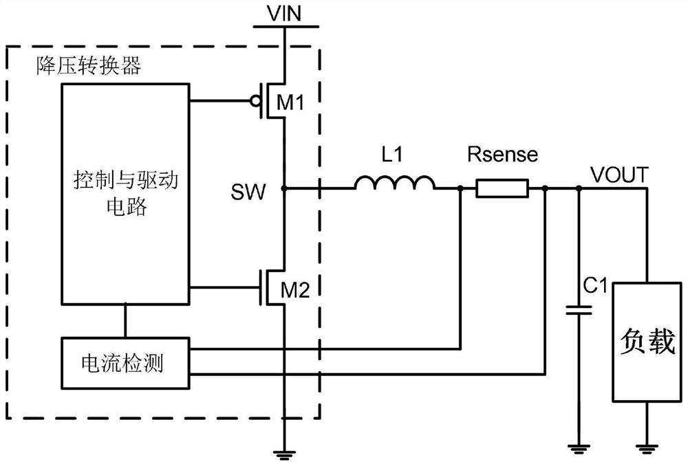
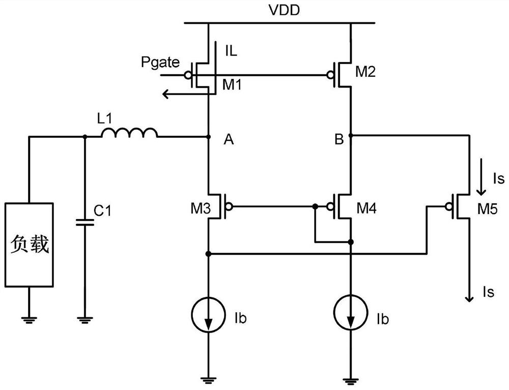
[0006] Among them, the disadvantage of method (1) is that the series sampling resistor Rsense will greatly reduce the conversion efficiency on the power transmission path. Usually, the on-resistance Rdson of a general power transistor is about 10-300 ohms. If a 100 ohm is connected in series Ohm sampling resistor, the sampling resistor Rsense is even greater than Rdson, the performance of the power tube is greatly affected, and the resistance of 100m ohm is difficult to have high enough precision, and additional chip pins need to be added, resulting in method (1) It is rarely used in practical applications; the disadvantage of method (2) is that it can only obtain peak current, such as Figure 5 As shown, since the peak current is composed of DC current and ripple current, the ripple current will vary with the input voltage, output voltage and inductance value, so the peak current cannot really accurately reflect the average current
In DCM (discontinuous current mode), there will be a period of time in each cycle that the current is zero, and the peak current cannot represent the average current.

Method used


Image

  • An average current detection circuit applied to dc-dc converter
  • An average current detection circuit applied to dc-dc converter
  • An average current detection circuit applied to dc-dc converter

Examples


Embodiment Construction

[0020] Embodiments of the present invention are described below through specific examples, and those skilled in the art can easily understand other advantages and effects of the present invention from the content disclosed in this specification. The present invention can also be implemented or applied through other different specific embodiments, and various modifications or changes can be made to the details in this specification based on different viewpoints and applications without departing from the spirit of the present invention. It should be noted that, in the case of no conflict, the following embodiments and features in the embodiments can be combined with each other.

[0021] It should be noted that the diagrams provided in the following embodiments are only schematically illustrating the basic ideas of the present invention, and only the components related to the present invention are shown in the diagrams rather than the number, shape and shape of the components in ...


PUM


Abstract

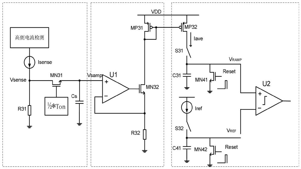
The invention provides an average current detection circuit applied to a DC-DC converter, which relates to the field of integrated circuits. The average current detection circuit includes an average current sampling module, a current conversion module, and an integral comparison module connected in sequence, and the average current sampling module It includes a high-side current detection circuit, a resistor R31, and an NMOS transistor MN31; the current conversion module includes an operational amplifier U1, an NMOS transistor MN32, and a resistor R32; the integral comparison module includes a PMOS transistor MP32, a switch S31, a capacitor C31, and an NMOS transistor MN41 , comparator U2, NMOS tube MN42, capacitor C41, switch S32; the average current detection circuit of the present invention will not affect the conversion efficiency, and can allow DC-DC to switch between PWM mode and PFM mode at a constant load current, with high conversion Efficiency, strong versatility and precision.

Description

technical field [0001] The invention relates to the field of integrated circuits, in particular to an average current detection circuit applied to a DC-DC converter. Background technique [0002] In the DC-DC step-down converter, the pulse width modulation mode (PWM mode) has higher conversion efficiency at heavy loads and lower conversion efficiency at light loads, while the pulse frequency modulation mode (PFM mode) has higher conversion efficiency at light loads. When the conversion efficiency is higher. In order to improve the conversion efficiency of light loads, usually heavy loads work in PWM mode, and light loads work in PFM mode. Therefore, a load current detection circuit is usually required to switch between PWM mode and PFM mode at a suitable fixed load current. So that the chip has high conversion efficiency in the whole load range. [0003] Traditional load current detection methods are mainly divided into two types: [0004] (1) if figure 1 As shown, a sam...

Claims


Application Information

Patent Timeline
Patent Type & Authority Patents(China)
IPC IPC(8): H02M3/156H02M3/158G01R19/00
CPCG01R19/0092H02M3/156H02M3/158H02M1/0009
Inventor 丁万新刘政清潘文捷谢阔
Owner SHANGHAI CHIPANALOG MICROELECTRONICS LTD
Learn More