Eureka AIR delivers breakthrough ideas for toughest innovation challenges, trusted by R&D personnel around the world.

Industrial waste sewage treatment process

A technology for sewage treatment and sewage treatment equipment, which is applied in the fields of filtration and separation, separation methods, chemical instruments and methods, etc., can solve the problems of reduced filtration capacity of filtration equipment, ineffective filtration of impurities, poor sewage filtration effect, etc. The effect of small pollution, saving production cost and improving scraping effect

Active Publication Date: 2020-06-23
陕西祥宇环保科技有限公司
View PDF5 Cites 1 Cited by
  • Summary
  • Abstract
  • Description
  • Claims
  • Application Information

AI Technical Summary

Problems solved by technology

[0003] 1. Some structures in common sewage treatment devices are simply driven by mechanical means, but ignore the kinetic energy and potential energy that can be generated by the sewage itself, thereby greatly reducing the utilization rate of sewage. At the same time, the sewage is filtered in the injection device. Since there is no single direction flow, it is easy to splash around, so the impurities in the sewage are easy to adhere and accumulate on the inner surface of the device and other structures, which makes the sewage filtration effect poor;
[0004] 2. The impurities filtered by the filter device cannot be stored in a timely manner. The impurities gradually accumulate on the filter device and cause the filter capacity of the filter device to decrease, thereby greatly reducing the degree of filtration of sewage, and the impurities accumulated on the filter device It is not conducive to the collection operation of the operator, and at the same time, the filter device filters the sewage less frequently, so that the impurities in the sewage cannot be effectively filtered

Method used


Image

  • Industrial waste sewage treatment process
  • Industrial waste sewage treatment process
  • Industrial waste sewage treatment process

Examples


Embodiment Construction

[0037] The embodiments of the present invention will be described in detail below with reference to the accompanying drawings, but the present invention can be implemented in many different ways as defined and covered by the claims.

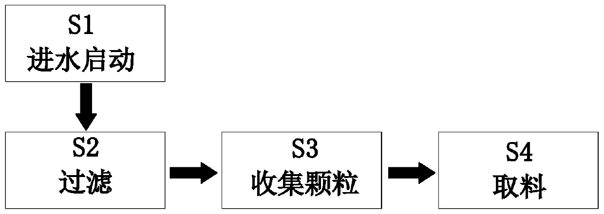
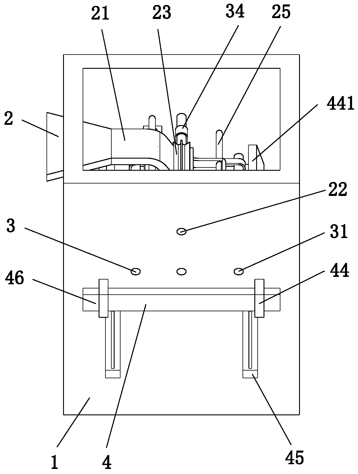
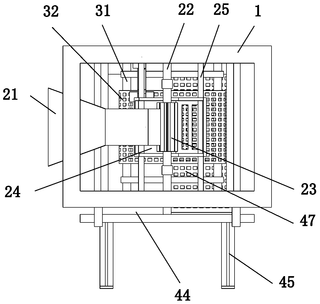
[0038] like Figure 1 to Figure 10 As shown, an industrial waste sewage treatment process uses an industrial waste sewage treatment device. The industrial waste sewage treatment device includes a tank body 1, a driving device 2, a filtering device 3 and a storage device 4. The specific treatment process of the sewage treatment plant for the treatment of industrial waste water is as follows:

[0039] S1. Water inlet start: inject sewage into the tank body 1 through the water inlet pipe 21, use the height difference between the left and right ends of the water inlet pipe 21 to drive the rotating gear 23 to rotate counterclockwise through the impact of the water flow, and the rotating gear 23 drives the rotating shaft 22 to rotate synchronously. Th...


PUM


Abstract

The invention relates to an industrial waste sewage treatment process. An industrial waste sewage treatment device is used in the method. The industrial waste sewage treatment device comprises a tankbody, a driving device, a filtering device and a collecting and storing device, the driving device is mounted at the upper end of the interior of the tank body; the filtering device is arranged on thelower side of the driving device; the filtering device is in sliding fit with the tank body; the collecting and storing device is mounted at the lower end in the tank body; the collecting and storingdevice is positioned on the lower side of the filtering device; according to the invention, industrial waste sewage treatment is carried out by using the design concept of converting water energy into mechanical energy; by means of the structural design, the utilization rate of sewage is increased to the maximum extent, meanwhile, pollution is reduced, the production cost is saved, meanwhile, themultiple filtering structures are arranged to conduct multiple times of filtering treatment of different degrees on the sewage, and then the filtering effect of the sewage is improved so that subsequent retreatment and utilization can be facilitated.

Description

technical field [0001] The invention relates to the technical field of sewage treatment, in particular to an industrial waste sewage treatment process. Background technique [0002] Sewage refers to the polluted discharge water from life and production. Due to the addition of new substances in the water or changes in external conditions, the water deteriorates and cannot continue to maintain its original function. The water is referred to as sewage. The used water contains more organic matter and is easier to treat. According to the source of sewage, sewage can be defined as waste mixed with groundwater, surface water, snowstorms, etc. discharged from residential, institutional, commercial or industrial areas. According to the source of sewage, sewage can be divided into four types: industrial sewage, domestic sewage, commercial sewage and surface runoff. There are many types of sewage, among which industrial wastewater includes production wastewater, production sewage and c...

Claims


Application Information

Patent Timeline
IPC IPC(8): B01D36/02
CPCB01D36/02
Inventor 吴刘海何海峰
Owner 陕西祥宇环保科技有限公司
Why Eureka
Eureka Blog
Learn More