
Cosmetic raw material stirring device

A technology of stirring device and cosmetics, which is applied to mixers with rotating stirring devices, mixer accessories, transportation and packaging, etc., which can solve problems such as non-conforming production, low heating efficiency, discounted heating ring heating efficiency, etc., to improve processing efficiency , Improve the mixing effect

Inactive Publication Date: 2020-06-23
付锦涛
View PDF7 Cites 2 Cited by
  • Summary
  • Abstract
  • Description
  • Claims
  • Application Information

AI Technical Summary

Problems solved by technology

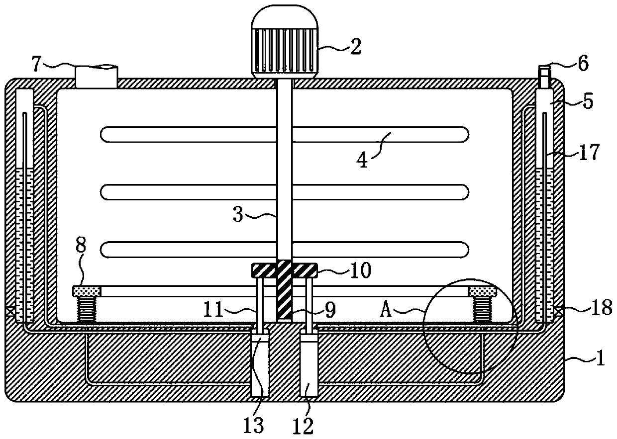
[0003] In the process of cosmetics processing, there is an important process, which is to put the cosmetic raw materials in a stirrer device for stirring, and during the stirring process, the cosmetic raw materials need to be heated at low temperature, so that various raw materials can be dissolved and mixed with each other faster. The cosmetic raw material mixer usually uses a fixed heating ring or a heating plate to heat the raw materials at the bottom of the mixing tank. Since the height of the mixing tank is high and the heating temperature is not high, even if there are stirring blades constantly stirring, it will still There is a shortage of low heating efficiency; and because the cosmetic raw materials need to be heated when they are stirred, the water in the raw materials will continue to evaporate and lose, which will cause the concentration of cosmetics to become higher and higher, which does not meet the needs of production; at the same time, the fixed heating ring In order not to touch the stirring mechanism during installation, there is generally a certain distance from the stirring mechanism, which leads to the fact that the raw materials near the heating ring cannot be stirred by the stirring blades during stirring, so they will be locally heated and adhere and condense when heated. On the ring, the heating efficiency of the heating ring is greatly reduced

Method used


Image

  • Cosmetic raw material stirring device
  • Cosmetic raw material stirring device

Examples


Embodiment Construction

[0017] The following will clearly and completely describe the technical solutions in the embodiments of the present invention with reference to the accompanying drawings in the embodiments of the present invention. Obviously, the described embodiments are only some of the embodiments of the present invention, not all of them.

[0018] In describing the present invention, it should be understood that the terms "upper", "lower", "front", "rear", "left", "right", "top", "bottom", "inner", " The orientation or positional relationship indicated by "outside", etc. is based on the orientation or positional relationship shown in the drawings, and is only for the convenience of describing the present invention and simplifying the description, rather than indicating or implying that the referred device or element must have a specific orientation, so as to Specific orientation configurations and operations, therefore, are not to be construed as limitations on the invention.

[0019] refe...


PUM


Abstract

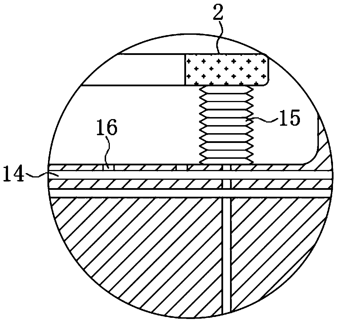
The invention discloses a cosmetic raw material stirring device. The stirring device comprises a stirring tank, a motor fixedly installed in the middle of the upper end of the stirring tank and an electric heating ring arranged in the stirring tank. The output shaft of the motor penetrates into the stirring tank and is coaxially and fixedly connected with a stirring shaft. Stirring blades are arranged on the side wall of the stirring shaft, and a feeding port is formed in the upper end of the stirring tank. A pumping mechanism, a driving mechanism, a reciprocating lead screw, a lead screw nutand a sliding plug are arranged; raw materials are stirred, at the same time, clean and wet air is introduced into the stirring tank; the stirring effect can be improved, the water loss of raw materials due to evaporation can be supplemented, the electric heating ring can be driven to move up and down in the raw materials, the raw materials can be heated more evenly, meanwhile, the auxiliary stirring effect is achieved, and the raw materials are prevented from adhering to and condensing on the electric heating ring so as to prevent the phenomenon that the heating efficiency of the electric heating ring is greatly reduced.

Description

technical field [0001] The invention relates to the technical field of cosmetic production equipment, in particular to a cosmetic raw material stirring device. Background technique [0002] With the development of society, women have become the main force of consumption in today's market, and cosmetics, as a high-consumable product that can improve women's beauty and quality of life, have an inestimable huge market demand. Therefore, the production and processing industry of cosmetics is also Then it became hot. [0003] In the process of cosmetics processing, there is an important process, which is to put the cosmetic raw materials in a stirrer device for stirring, and during the stirring process, the cosmetic raw materials need to be heated at low temperature, so that various raw materials can be dissolved and mixed with each other faster. The cosmetic raw material mixer usually uses a fixed heating ring or a heating plate to heat the raw materials at the bottom of the mi...

Claims


Application Information

Patent Timeline
Patent Type & Authority Applications(China)
IPC IPC(8): B01F7/18B01F13/02B01F15/06B01F33/40
CPCB01F33/402B01F27/90B01F35/91B01F35/93B01F2101/21
Inventor 付锦涛李媛
Owner 付锦涛
Learn More