Printing roll

A technology of printing rollers and round rods, applied in printing, printing machines, rotary printing machines, etc., can solve the problems of shortening the service life of printing rollers, different shades, incompleteness, etc., to shorten the service life and improve cleaning efficiency , Improve the effect of printing quality

Inactive Publication Date: 2020-06-23
倪敏跃
View PDF0 Cites 0 Cited by
  • Summary
  • Abstract
  • Description
  • Claims
  • Application Information

AI Technical Summary

Problems solved by technology

[0002] The printing roller is the core of the printing machine, and it is the basis for ensuring the correct transfer of printed graphics and the accuracy of graphic reproduction. When printing sheets, printing ink may remain on the surface of the printing roller, and uneven printing ink will occur during repeated printing. The problem of different shades will have a great impact on the printing quality. It must be cleaned, otherwise it will cause inconvenience to the next printing, which will increase the labor intensity and working hours of the workers.
[0003] However, the following problems exist in the cleaning of the current printing roller. 1. In the process of manual cleaning of the traditional printing roller, it is necessary to wipe the printing roller back and forth with a rag to achieve the purpose of cleaning. Although this method can remove the printing roller to a certain extent The ink on the ink is not thorough, the efficiency is low, and the risk of manual wiping is high; 2. The existing printing rollers do not have a cleaning function, and the printing roller cannot be cleaned in time, which shortens the use of the printing roller Long life, can clean the printing roller in time, improve the printing quality and cleaning efficiency of the printing roller

Method used


Image

  • Printing roll
  • Printing roll
  • Printing roll

Examples


Embodiment Construction

[0027] The embodiments of the present invention will be described in detail below with reference to the accompanying drawings, but the present invention can be implemented in many different ways defined and covered by the claims.

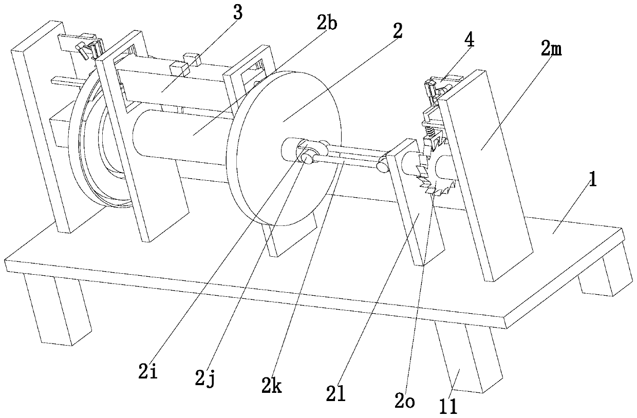
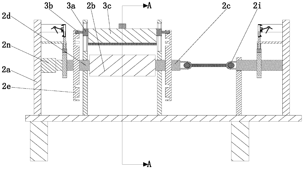
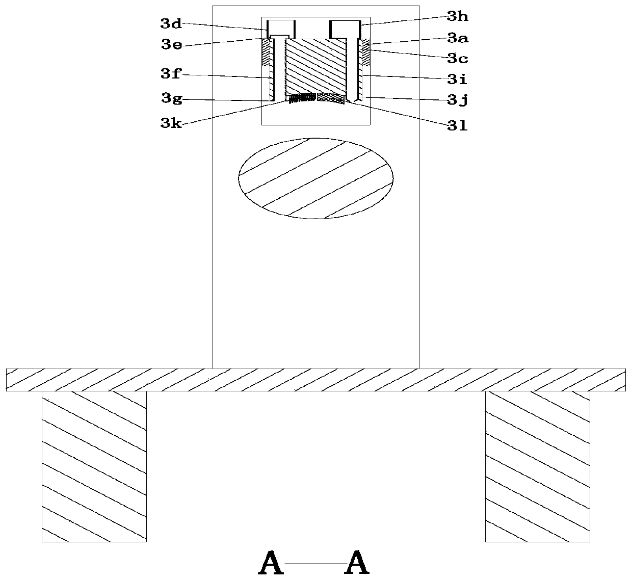
[0028] Such as Figure 1 to Figure 7 As shown, a printing roller includes a bottom plate 1, an energy storage device 2, a cleaning device 3 and a locking device 4. The middle end of the bottom plate 1 is equipped with an energy storage device 2, and the upper end of the energy storage device 2 is equipped with a cleaning device 3. , The energy storage device 2 is equipped with a locking device 4 .

[0029]The energy storage device 2 includes a support plate 2a, a printing roller 2b, a rotating shaft 2c, a rotating round rod 2d, a rotating disc 2e, a return spring 2f, a rotating round rod 2g, a connecting plate 2h, a connecting ring 2i, a power Round rod 2j, rubber rope 2k, flat plate 2l, square plate 2m, rotating motor 2n and ratchet 2o, the middle...


PUM


Abstract

The invention relates to a printing roll. The printing roll comprises a bottom plate, an energy storage device, a cleaning device and a locking device, wherein the energy storage device is installed at the middle end of the bottom plate; the cleaning device is installed at the upper end of the energy storage device; and the locking device is installed on the energy storage device. The printing roll is capable of solving the following problems existing during cleaning for an existing printing roll: 1, in a manual cleaning process for a traditional printing roll, a rag needs to be used for wiping the printing roll back and forth, so that a cleaning purpose is realized, and although the manner is capable of removing ink on the printing roll to a certain extent, the manner is not thorough, lowin efficiency, and high in manual wiping risk; and 2, the existing printing roll does not have a cleaning function, and is incapable of carrying out cleaning working on the printing roll in time, sothat the service life of the printing roll is shortened, and the cleaning working can be carried out on the printing roll in time, so that the printing quality for the printing roll is improved, and the cleaning efficiency for the printing roll is increased.

Description

technical field [0001] The invention relates to the technical field of printing consumables, in particular to a printing roller. Background technique [0002] The printing roller is the core of the printing machine, and it is the basis for ensuring the correct transfer of printed graphics and the accuracy of graphic reproduction. When printing sheets, printing ink may remain on the surface of the printing roller, and uneven printing ink will occur during repeated printing. The problem of different shades will have a great impact on the printing quality, and it must be cleaned, otherwise it will cause inconvenience to the next printing, which will increase the labor intensity and working hours of the workers. [0003] However, the following problems exist in the cleaning of the current printing roller. 1. In the process of manual cleaning of the traditional printing roller, it is necessary to wipe the printing roller back and forth with a rag to achieve the purpose of cleanin...

Claims


Application Information

Patent Timeline
IPC IPC(8): B41F35/00B41F13/08
CPCB41F13/08B41F35/00
Inventor 倪敏跃张盼盼张赛
Owner 倪敏跃
Why Eureka
Try Eureka