Spinning creel for a twisting machine

A technology for spinning bobbins and creels, which is applied in the fields of spinning bobbins, twisting machines, and ring twisting machines. It can solve the problem of interruption, yarn or filament breakage, uncontrollable and safe use, etc. problem, to achieve the effect of cheap manufacturing

Active Publication Date: 2020-06-23
索若技术两合股份有限公司
View PDF9 Cites 0 Cited by
  • Summary
  • Abstract
  • Description
  • Claims
  • Application Information

AI Technical Summary

Problems solved by technology

However, the exact position of the spinning package can no longer be determined and thus a controlled and safe use is no longer possible
At this point, the operation of the twisting machine with spinning creels can be adversely affected until the spinning bobbin is locked, whereby the yarn or filament breaks and the operation is interrupted

Method used


Image

  • Spinning creel for a twisting machine
  • Spinning creel for a twisting machine
  • Spinning creel for a twisting machine

Examples


Embodiment Construction

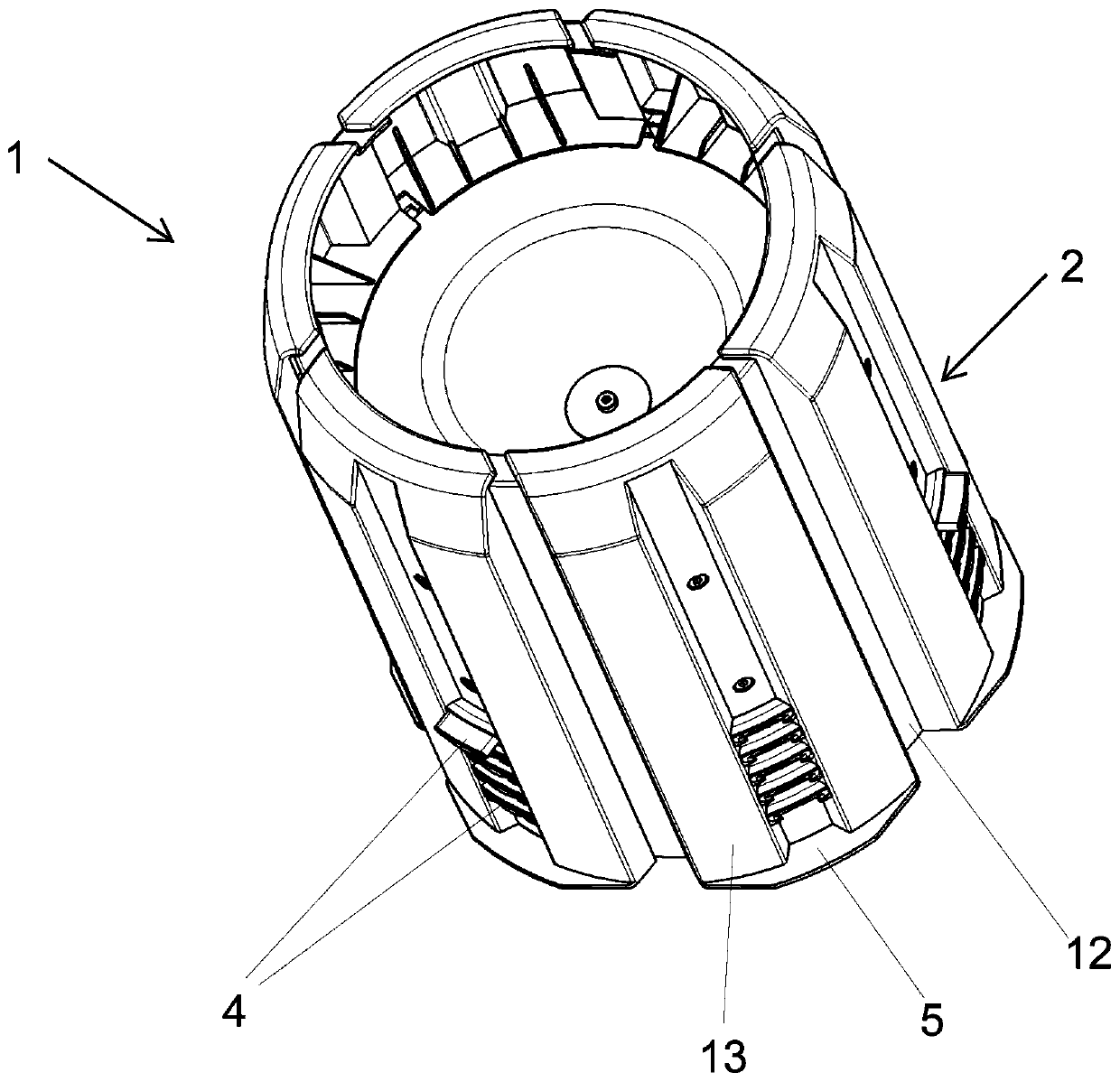
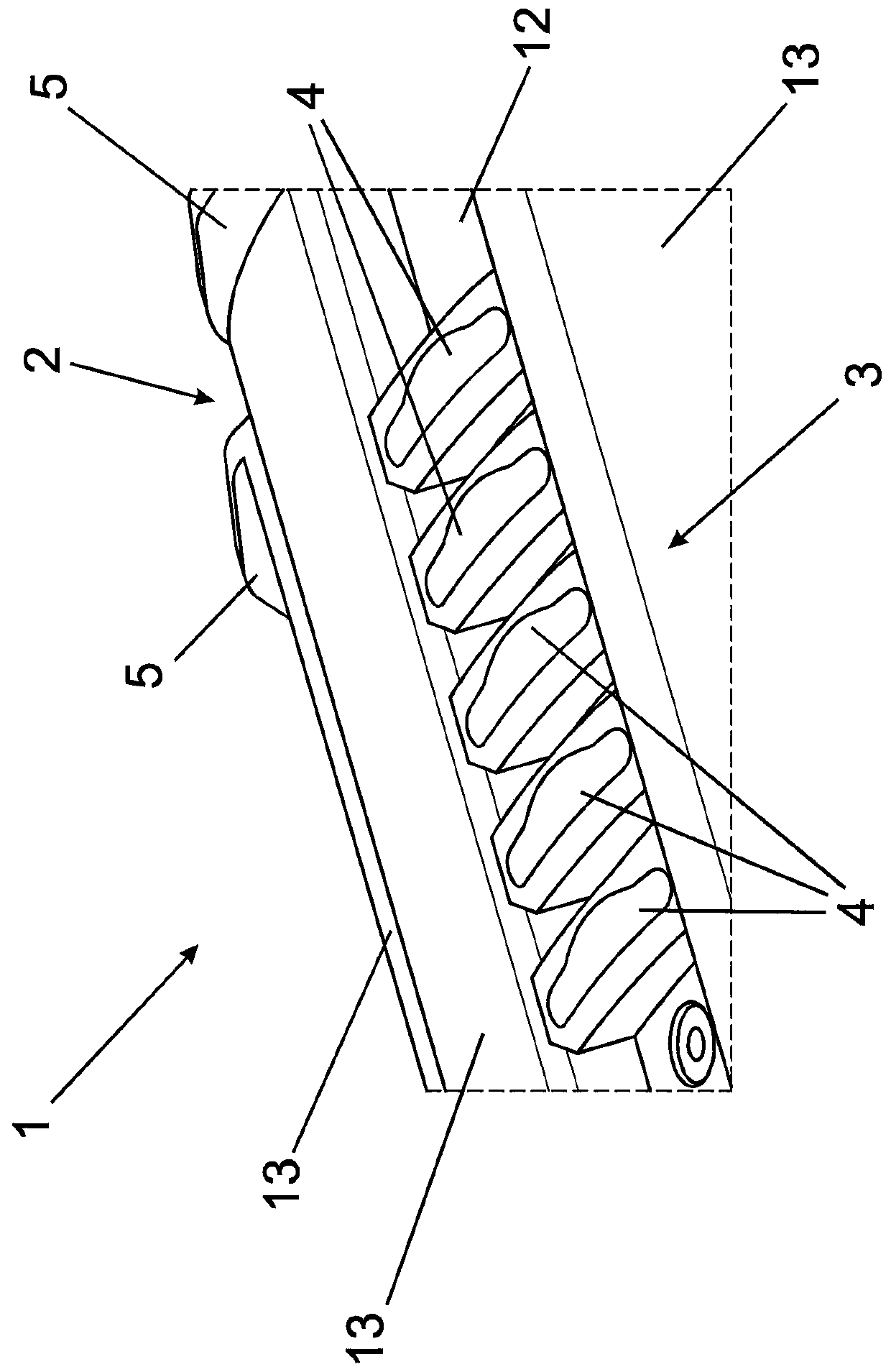
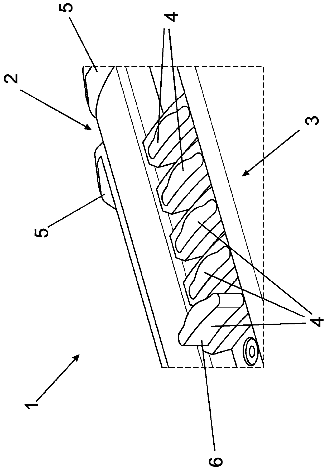
[0052] exist figure 1 as shown in Figure 1a In a spinning creel 1 for a high-efficiency ring twisting machine shown in part, the containing body 2 is arranged rotatably around the creel axis, so that the spinning The bobbin feeds the spinning bobbin yarn to the high-efficiency ring twisting machine. The spinning creel 1 here has an electric motor drive unit, which can rotate the receiving body 2 via the creel shaft.

[0053] The receiving body 2 has a main body 12 containing the creel shaft and a plurality of clamping bodies 13 arranged evenly distributed on the outer circumference of the receiving body 2, wherein the clamping bodies 13 are movable away from the main body 12 in the radial direction with respect to the creel shaft, so as to be able to The spinning bobbin pushed onto the receiving body 2 in the receiving area 3 is secured in a non-positive manner. Each clamping body 13 has at one end a fixed end stop 5 which delimits the end of the receiving area 3 in the di...


PUM


Abstract

The present invention relates to a spinning creel for a twisting machine, in particular to a ring twisting machine. The spinning creel has an accommodating body rotatably mounted around the spinning creel axis, and the accommodating body has an accommodating area for holding bobbins on the accommodating body. In order to achieve safe and reliable operation of spinning creels with non-standardizedspinning bobbins of different lengths, it is stipulated that at least one stopper can be adjusted and moved between a use position and a lowered position in the accommodating area, so that in the useposition, the accommodating area is shortened to accommodate shortened spinning bobbins, and in the lowered position, a conventional spinning bobbin can be placed in the accommodating area beyond thestop.

Description

technical field [0001] The invention relates to a spinning creel for a twisting machine, in particular a ring twisting machine, having a receptacle mounted rotatably around the creel axis, the receptacle having a receptacle for placing spinning bobbins on the receptacle . The invention also relates to a twisting machine, in particular a ring twisting machine, which has at least one spinning creel. Finally, the invention relates to a method of using spinning creels. Background technique [0002] Various arrangements of spinning creels are disclosed by prior art such as publication CN204369314U and are used for rotatably supporting spinning bobbins together with the yarns or filaments to be twisted. For this reason, standardized spinning bobbins are generally placed on spinning creels and are held stably and securely by the spinning creels during use. [0003] However, it is also possible to use spinning bobbins which are relatively small and, in particular, relatively shor...

Claims


Application Information

Patent Timeline
Patent Type & Authority Applications(China)
IPC IPC(8): B65H49/32B65H49/34B65H49/38
CPCB65H49/32B65H49/34B65H49/38B65H2701/31B65H75/242B65H75/24B65H54/543D01H1/02D01H7/04D01H7/16
Inventor J·奇施斯基
Owner 索若技术两合股份有限公司
Why Eureka
Try Eureka