
Installation detection method and device for remote control device

A technology of a remote control device and a detection method, applied in image data processing, instruments, computing, etc., can solve the problems of low installation and detection efficiency of the LCD screen of the remote control, effective detection of parts that cannot be blocked, etc.

Pending Publication Date: 2020-06-23
ZHUHAI GREE INTELLIGENT EQUIP CO LTD +1
View PDF4 Cites 2 Cited by
  • Summary
  • Abstract
  • Description
  • Claims
  • Application Information

AI Technical Summary

Problems solved by technology

[0004] The embodiment of the present invention provides a method and device for installation and detection of a remote control device, so as to at least solve the technical problem in the related art that the installation and detection efficiency of the LCD screen of the remote control is low and the blocked part cannot be effectively detected

Method used


Image

  • Installation detection method and device for remote control device
  • Installation detection method and device for remote control device
  • Installation detection method and device for remote control device

Examples


Embodiment 1

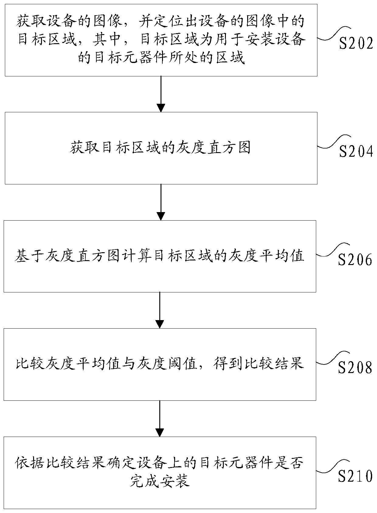
[0032] According to an embodiment of the present invention, an embodiment of a method for detecting installation of a remote control device is provided. It should be noted that the steps shown in the flow chart of the accompanying drawings can be executed in a computer system such as a set of computer-executable instructions, and , although a logical order is shown in the flowcharts, in some cases the steps shown or described may be performed in an order different from that shown or described herein.

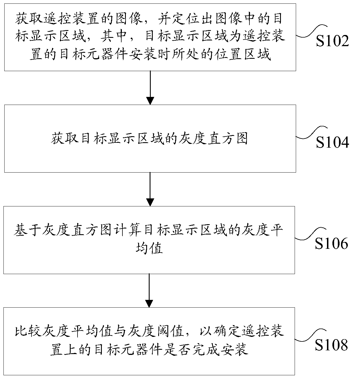
[0033] figure 1 is a flow chart of an optional installation detection method for a remote control device according to an embodiment of the present invention, such as figure 1 As shown, the method includes the following steps:

[0034] Step S102, acquiring the image of the remote control device, and locating the target display area in the image, wherein the target display area is the position area where the target components of the remote control device are installed;

[0035] ...

Embodiment 2

[0068] The present invention will be described below in conjunction with another optional embodiment. Each unit included in the device for detecting installation of a remote control device involved in the following embodiments corresponds to each implementation step in the method for detecting installation of a remote control device in the above embodiments. The present invention will be described in detail below in conjunction with each unit.

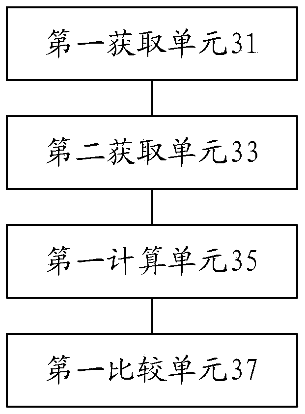
[0069] image 3 is a schematic diagram of an optional installation detection device for a remote control device according to an embodiment of the present invention, such as image 3As shown, the installation detection device may include: a first acquisition unit 31, a second acquisition unit 33, a first calculation unit 35, and a first comparison unit 37, wherein,

[0070] The first acquiring unit 31 is configured to acquire an image of the remote control device, and locate a target display area in the image, wherein the target displ...


PUM


Abstract

The invention discloses an installation detection method and device for a remote control device. The method comprises the steps that an image of the remote control device is acquired, a target displayarea in the image is positioned, and the target display area is a position area where a target component of the remote control device is located when the target component is installed; obtaining a gray histogram of the target display area; calculating a gray average value of the target display area based on the gray histogram; and comparing the gray scale average value with a gray scale thresholdvalue to determine whether the target component on the remote control device is installed or not. According to the invention, the technical problems that the installation and detection efficiency ofthe remote controller liquid crystal screen is low and the shielded part cannot be effectively detected in the prior art are solved.

Description

technical field [0001] The invention relates to the technical field of equipment detection, in particular to a method and device for installation detection of a remote control device. Background technique [0002] In related technologies, most equipment (for example, remote control) manufacturers rely on manual labor to assemble target equipment. This assembly method not only requires a lot of labor, but also has too low efficiency, and the increase in labor costs makes manufacturers We have to consider automatic assembly of equipment through automated production lines. Machine assembly requires a detection and judgment process, including the assembly of LCD screens, wiring, and equipment housings. It is necessary to automatically judge whether the assembly is in place. The current detection process is mostly In the process of component assembly, install one detection once, but this detection method often achieves effective detection of covered objects. For example, during t...

Claims


Application Information

Patent Timeline
Patent Type & Authority Applications(China)
IPC IPC(8): G06T7/00G06T7/11G06T7/44G06T7/70
CPCG06T7/001G06T7/11G06T7/44G06T7/70G06T2207/10004G06T2207/30121
Inventor 杨顺波邓及翔宋明岑
Owner ZHUHAI GREE INTELLIGENT EQUIP CO LTD
Learn More