Wood stick sharpening equipment for garden fence construction
A technology of fences and sticks, applied in the direction of manufacturing tools, wood processing appliances, special forming/shaping machines, etc., can solve the problems of large effort, low efficiency, and different cutting shapes of workers, and achieves reduced operation difficulty, The effect of improving work efficiency
- Summary
- Abstract
- Description
- Claims
- Application Information
AI Technical Summary
Problems solved by technology
Method used
Image
Examples
Embodiment 1
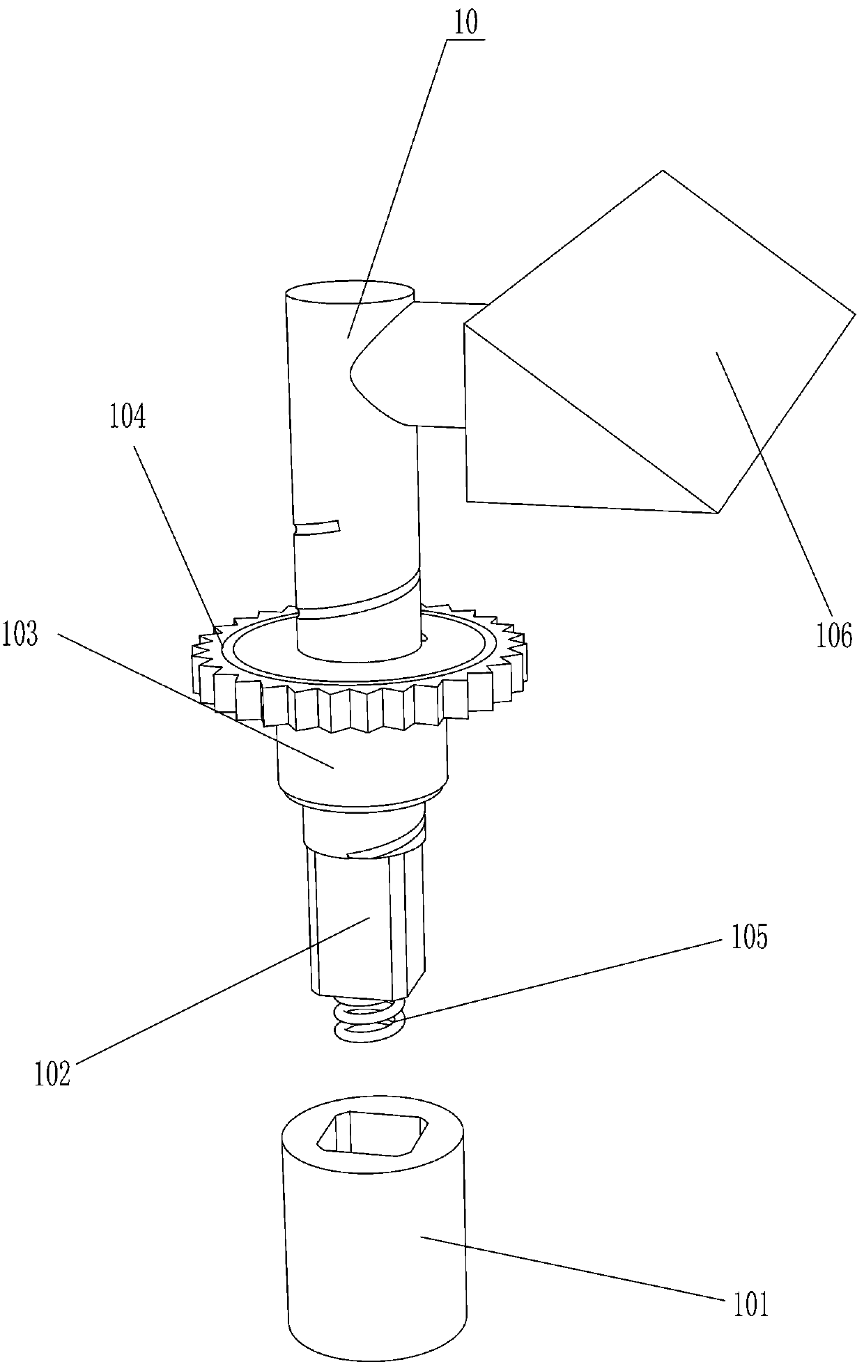
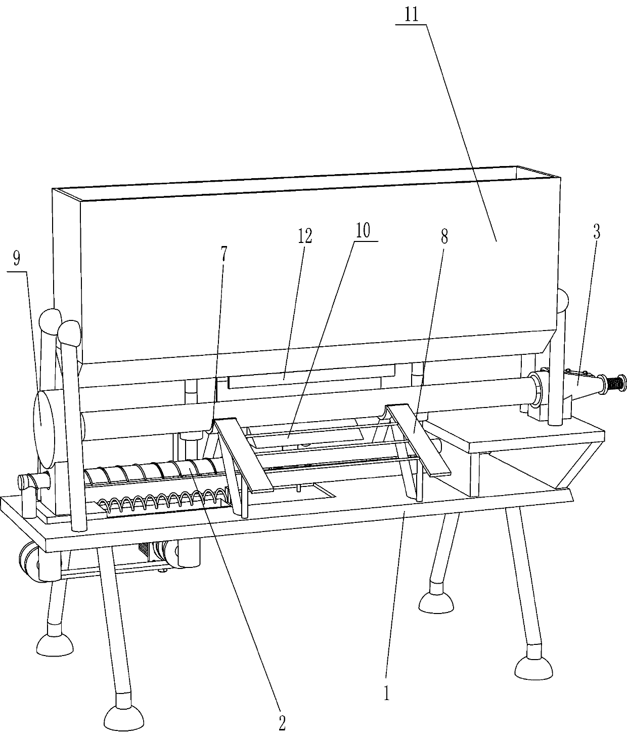
[0025] A wooden stick sharpening equipment for garden fence construction, such as Figure 1-7 As shown, it includes a base 1, a horizontal screw 2, a reel 3, a disc 4, a push spring 5, a push rod 6, a pallet 7, a guide plate 8, a push assembly 9 and an unloading mechanism 10, and the base 1 A horizontal screw 2 is installed horizontally on the top of the base 1, and a reel 3 is fixedly connected to the top right side of the base 1. A cutter head is provided on the reel 3. The shape of the reel 3 is conical, and a disc is connected to the tail end of the reel 3. 4. A push rod 6 is slidingly provided in the middle of the disc 4, and a push spring 5 is connected between the tail end of the push rod 6 and the disc 4, and the push spring 5 is set on the push rod 6, and the middle of the top of the base 1 A pallet 7 is provided, the front side of the pallet 7 is connected with a material guide plate 8, a pushing assembly 9 is installed on the left side of the base 1, a discharge mec...
Embodiment 2
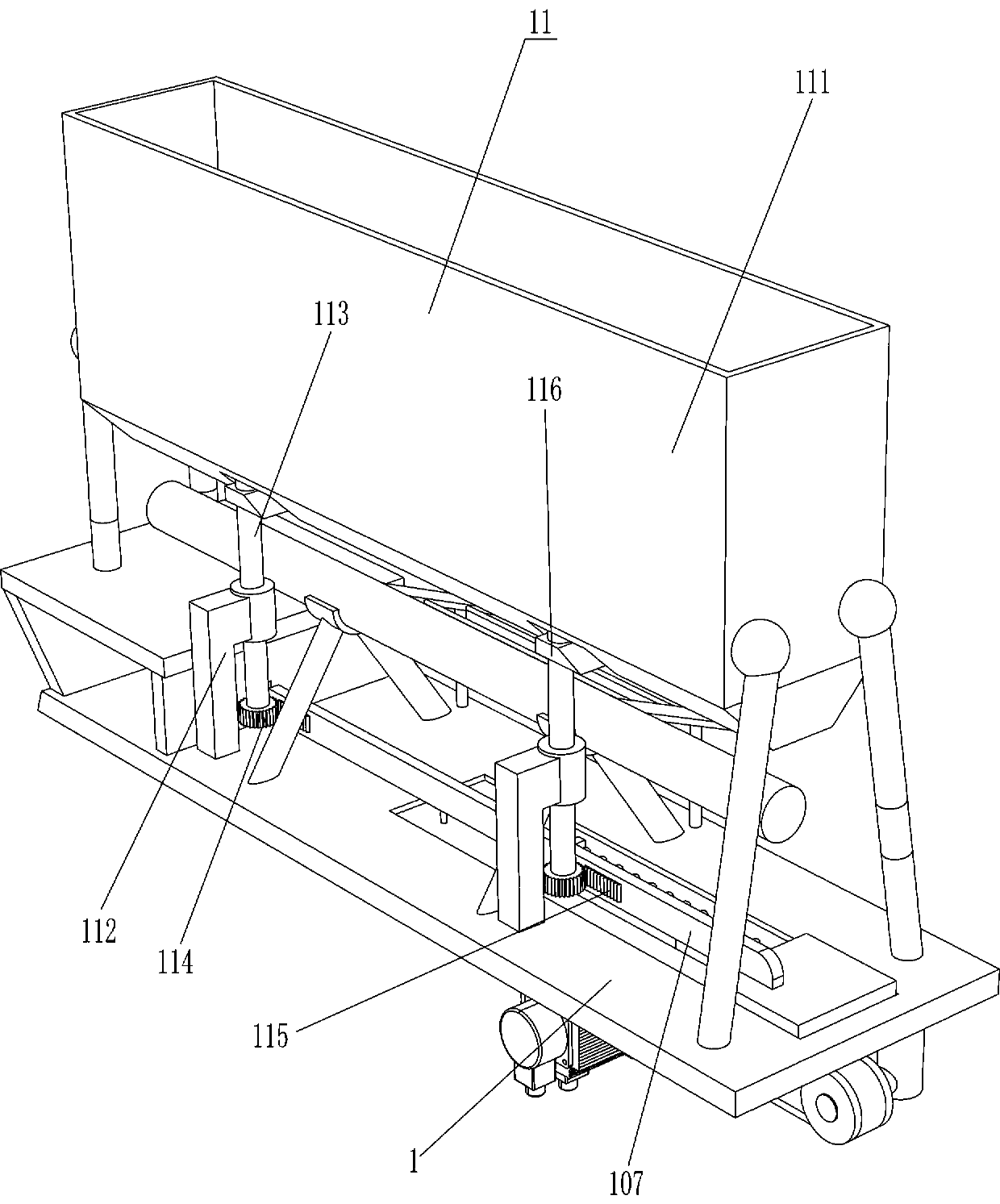
[0030] On the basis of Example 1, as Figure 8-9As shown, it also includes a blanking device 11. The blanking device 11 includes a material frame 111, a pillar 112, a rotating shaft 113, a cylindrical gear 114, a second rack 115, a second stopper 116, a third stopper 117 and an arc. Plate 118, a material frame 111 is installed on the top of the base 1, two pillars 112 are connected to the rear side of the top of the base 1, and the two pillars 112 are symmetrically arranged on the left and right. Vertically arranged, the bottom of the rotating shaft 113 is connected with a cylindrical gear 114, the left and right sides of the rear end surface of the push plate 107 are connected with a second rack 115, the second rack 115 meshes with the cylindrical gear 114, and the top and top of the rotating shaft 113 are respectively A second stopper 116 and a third stopper 117 are provided, and the angle between the second stopper 116 and the third stopper 117 is 90 degrees, and arc-shaped...
PUM
 Abstract
Description
Claims
Application Information
 - R&D
- Intellectual Property
- Life Sciences
- Materials
- Tech Scout
- Unparalleled Data Quality
- Higher Quality Content
- 60% Fewer Hallucinations
Browse by: Latest US Patents, China's latest patents, Technical Efficacy Thesaurus, Application Domain, Technology Topic, Popular Technical Reports.
© 2025 PatSnap. All rights reserved.Legal|Privacy policy|Modern Slavery Act Transparency Statement|Sitemap|About US| Contact US: help@patsnap.com


