Belt Feeding Mechanism of Hemming Device for Plate-Shaped Workpiece
What is Al technical title?
Al technical title is built by PatSnap Al team. It summarizes the technical point description of the patent document.
A technology of wrapping device and workpiece, applied in the direction of electrical components, printed circuits, printed circuit manufacturing, etc., can solve the problems of manual wrapping and pasting operation of leaks, poor consistency of wrapping and pasting state, cumbersome and other problems, so as to overcome the unreliable manual operation, Easy mass production, highly systematic effect
Active Publication Date: 2021-10-29
BEIBU GULF UNIV
View PDF4 Cites 0 Cited by
Summary
Abstract
Description
Claims
Application Information
AI Technical Summary
This helps you quickly interpret patents by identifying the three key elements:
Problems solved by technology
Method used
Benefits of technology
Problems solved by technology
[0003] In order to solve the difficulties such as poor consistency of wrapping state, deficiencies such as partial sticking, folds, and leaks, and manual wrapping operation is cumbersome, the invention provides a belt feeder mechanism for a plate-shaped workpiece edge wrapping device
Method used
Image
Click on the blue label to locate the original text in one second.
Reading with bidirectional positioning of images and text.
Examples
Embodiment Construction
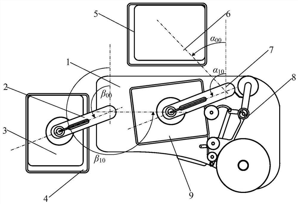
[0032] exist figure 1 One embodiment of the present invention shown-in the top view schematic diagram of plate-shaped workpiece hemming method: the overall configuration described in the plate-shaped workpiece hemming method includes abutment 1, blanking mechanism 2, packaged parts, blanking car 4, Loading cart 5, items to be packaged 6, feeding mechanism 7, belt feeding mechanism 8 and packaged items 9. Abutment 1, as the main workbench, cabinet body and work and bearing surface of the overall device of the system, is located in the middle right of the workplace. The unloading mechanism 2 is used as a system device for grasping, transferring and lowering the package, and is assembled on the left end above the abutment 1 . The finished package 3 is the work object of the system device—the workpiece that has been hemmed is grasped, transferred, and lowered by the unloading mechanism 2, and placed in the unloading car 4 in turn. The unloading vehicle 4 is used as a transfer de...
PUM
Abstract
The utility model relates to a belt feeding mechanism of a plate-shaped workpiece hemming device. The belt feeding mechanism is assembled on the right side of the feeding mechanism above the abutment, and mainly includes a guide pulley, a support shaft, a tape roll, a support reel, an end seat plate, a rocker motor, a rocker arm, an elastic arm, a connecting arm, a cutting Head drive coil, connecting rod, heating cable, cutting head, cutter, pulley, adjustment handle and pinch pulley. The guide pulley is a wheel disc part with a wheel edge groove, which is assembled on the left inner end of the end seat disc. The matching hole of the supporting belt shaft and the tape roll forms a rotational fit. The support reel is a disc with a support shaft. The disc body and the central axis of the support shaft are sleeved with an impermeable shaft sleeve hole at the upper end. The elastic arm is extended outward from the center of the outer side of the end seat plate, the upper right inner corner is equipped with a belt tray, the upper left inner corner is equipped with a pulley, and the lower middle left outer part is installed with a cut-end driving coil. The rocker arm motor is installed on the right outer end of the abutment, that is, the right side of the loading column. The head end of the rocker arm is fastened to the output shaft end of the rocker arm motor, and the elastic arm and connecting arm are assembled at the tail end.
Description
technical field [0001] The invention relates to a method for wrapping the side of a flat workpiece. Background technique [0002] In many production lines of flat-shaped products, there is a process of side-wrapping flat-shaped workpieces, especially for circuit board manufacturers. This type of production process is: wrapping the entire periphery of the flat-shaped workpiece with a special adhesive tape. At present, this kind of process is all done manually, and the result is that the consistency of the wrapping state is poor, and there are defects such as partial sticking, folds, and leaks in different parts. For the usual large and heavy boards, manual operation is more difficult. This is a bottleneck that seriously affects the process of related product production lines, hindering the automation of the entire production process. Therefore, it is urgent to develop an automatic method that can ensure the consistency of the wrapping state and replace the heavy manual ope...
Claims
Application Information
Patent Timeline
Application Date:The date an application was filed.
Publication Date:The date a patent or application was officially published.
First Publication Date:The earliest publication date of a patent with the same application number.
Issue Date:Publication date of the patent grant document.
PCT Entry Date:The Entry date of PCT National Phase.
Estimated Expiry Date:The statutory expiry date of a patent right according to the Patent Law, and it is the longest term of protection that the patent right can achieve without the termination of the patent right due to other reasons(Term extension factor has been taken into account ).
Invalid Date:Actual expiry date is based on effective date or publication date of legal transaction data of invalid patent.