
A kind of supercritical fluid jigger

A supercritical fluid and dye jigger technology, which is applied in the processing of textile material carriers, textile material containers, liquid/gas/steam textile materials, etc., can solve the problem of low heat transfer efficiency of jacketed heat exchangers, dye dissolvers, etc. Difficult installation, high fabric tension, etc.

Active Publication Date: 2020-12-22
SHANDONG UNIV +1
View PDF4 Cites 0 Cited by
  • Summary
  • Abstract
  • Description
  • Claims
  • Application Information

AI Technical Summary

Problems solved by technology

[0005] 1. The fan seal and the cloth roller seal are installed inside the dyeing jigger. Due to the high working temperature and no cooling measures, the life of the sealing components is short. In addition, the entire non-quick opening cylinder head needs to be disassembled and replaced after replacement, which takes time. strenuous
[0006] 2. It is not suitable to adopt flat cover structure for non-quick start jigger cylinder head of large-diameter dyeing jiggers that people can enter
[0007] 3. For the jigger cylinder with layer-wrapped structure, as the diameter of the cylinder increases, under the same pressure, the wall thickness of the cylinder will increase accordingly, and the number of layers will also increase accordingly. Thick-walled cylinder and The gap between the laminates causes the heat transfer efficiency of the jacketed heat exchanger to be low, and the heat transfer effect is poor
[0008] 4. Since the dye dissolver is simply designed as a frequently disassembled part, not only the dye dissolver needs to be disassembled when replacing the dye, but also the dye dissolver needs to be disassembled every time the dye is added
The dyeing jigger needs to be frequently pushed and pulled out together with the quick-opening cylinder head, but the fan is fixed on the non-quick-opening cylinder head because it needs to be driven by the motor drive shaft, and cannot move together with the fixed support plate at the non-quick-opening end. After being pushed into the inner cavity of the jigger, the fan inlet and the non-quick opening fixed support plate tuyere cannot guarantee accurate docking and effective sealing
[0010] 6. Only the simple clamp opening and closing structure of the quick-start cylinder head opening and closing structure of the jigger is given, and no specific implementation plan is given
[0011] 7. The separate pull rod set in the internal structure affects the layout of the internal structure and reduces the utilization efficiency of the space in the dyeing vat
[0012] 8. The layout of the guide roller is unreasonable, which makes the installation of the dye dissolver difficult, and the efficiency of some return paths is low. The fabric is too close to the dye dissolver, which affects the supercritical fluid with dye dissolved, that is, the flow of dyeing fluid, and the return at the guide roller The angle is small, which increases the friction and makes the fabric tension too large

Method used


Image

  • A kind of supercritical fluid jigger
  • A kind of supercritical fluid jigger
  • A kind of supercritical fluid jigger

Examples


Embodiment 1

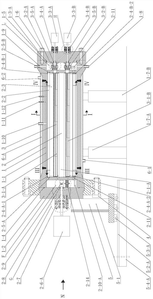
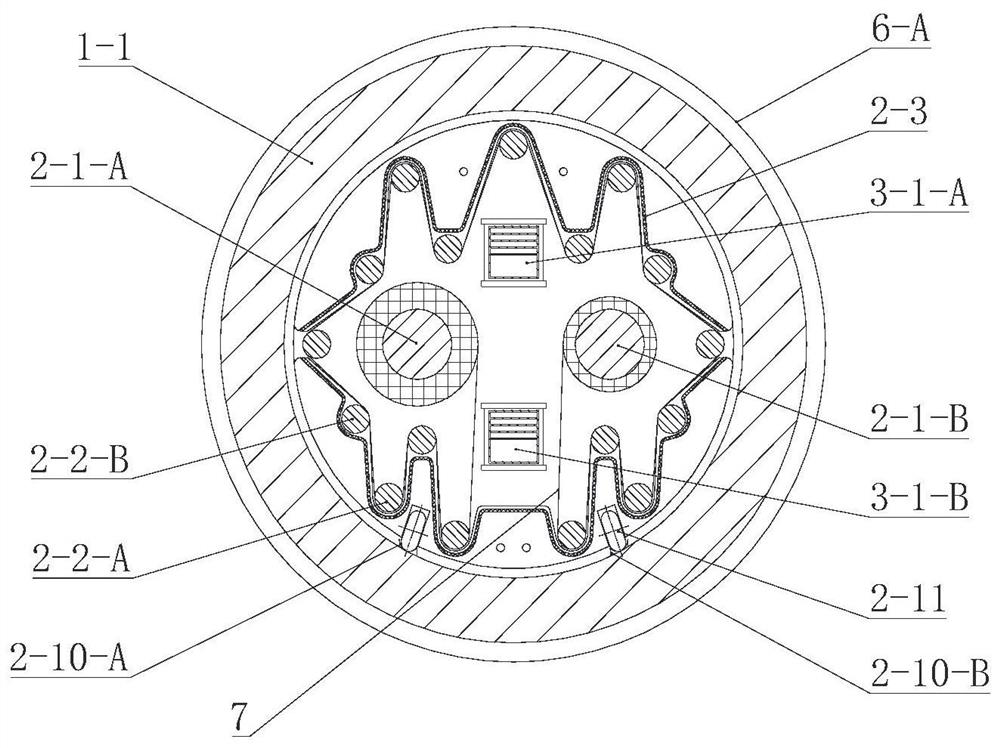
[0089] This embodiment discloses a supercritical fluid jigger with a small-diameter jigger structure that is difficult for people to enter and exit. The inner diameter of the cylinder body 1-1 is less than 800mm, and it has a non-quick opening cylinder cover 1-3-A, such as figure 1 , Figure 3-1 , Pic 4-1 , Figure 4-2 , Figure 5 , Figure 6-1 , Figure 6-2 , Figure 7-1 , Figure 7-2 , Figure 8-1 , Figure 9-1 , Figure 9-2 , Figure 9-3 , Figure 9-4 , Figure 10-1 , Figure 10-2 , Figure 10-3 , Figure 10-4 , Figure 10-5 , Figure 10-6 shown.

[0090] The supercritical fluid jigger with small diameter jigger structure is composed of jigger 1, jigger assembly 2, built-in dye dissolving circulation device 3, clamp opening and closing device 4, cloth roller sliding support device 5 and jacket heat exchanger 6 -A composition.

[0091] Such as figure 1 , the jigger vat 1 is mainly composed of a cylinder body 1-1, a quick opening cylinder cover 1-2, a non...

Embodiment 2

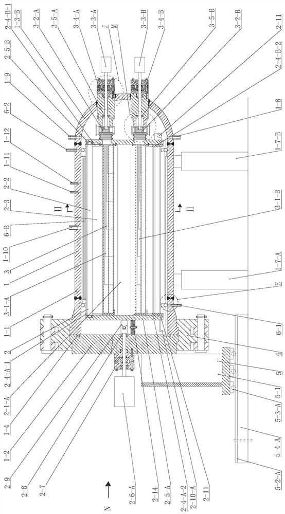
[0144] This embodiment discloses a supercritical fluid jigger with a large-diameter jigger structure that people can enter and exit. The inner diameter of the cylinder body 1-1 is greater than 800mm, and there is a non-detachable cylinder head 1-3-B, such as figure 2 , Figure 3-2 , Figure 3-3 , Pic 4-1 , Figure 4-2 , Figure 5 , Figure 6-1 , Figure 6-3 , Figure 7-1 , Figure 7-2 , Figure 8-2 , Figure 9-1 , Figure 9-2 , Figure 9-3 , Figure 9-4 , Figure 10-1 , Figure 10-2 , Figure 10-3 , Figure 10-4 , Figure 10-5 , Figure 10-6 Shown, the difference between its structure and embodiment 1 is: as figure 2 , the rear end part of the cylinder body 1-1 in this embodiment adopts the structure of the non-detachable cylinder head 1-3-B, and the non-detachable cylinder head 1-3-B is a hemispherical shell whose diameter is the same as that of the cylinder body 1-3-B. 1 is matched with the cylinder body 1-1 by welding, and the supercritical fluid mediu...


PUM


Abstract

The invention discloses a supercritical fluid jigger, which comprises a jigger vat, a jigger assembly, a built-in dye dissolving circulation device, a clamp opening and closing device, a cloth roller sliding support device and a heat exchanger; The sealing letter is set outside the cylinder body and equipped with a cooling device, which not only ensures reliable sealing, but also prolongs the life of the sealing ring, and makes it unnecessary to open the cylinder head when replacing the sealing ring, making replacement and installation more convenient; The fast start adopts non-detachable cylinder head, which saves the sealing structure and ensures good sealing performance; for large-diameter jigger cylinders, a built-in heat exchanger is used to ensure heat exchange efficiency; more reasonable and efficient fixed-position guide rollers are adopted And the layout of the guide rollers at the opening and closing position, the fabric is unfolded one inside and one outside, which increases the effective exposure area of ​​the fabric; 4 kinds of clamp opening and closing devices are designed to ensure the efficiency and safety of quick opening cylinder head opening and closing; improved dye The dissolver structure improves the installation efficiency.

Description

technical field [0001] The invention relates to a textile product dyeing device, in particular to a supercritical fluid dyeing device. Background technique [0002] Supercritical fluid dyeing technology, using supercritical fluid, especially supercritical carbon dioxide instead of water as the dyeing medium to dissolve dyes, has strong solubility and good diffusivity, which can save a lot of water resources and completely solve the problem of wastewater pollution while reducing dyeing time and reducing energy consumption. Therefore, the research and development of supercritical fluid dyeing device has a positive role in promoting the development of the fabric dyeing industry in the direction of environmental protection, low energy consumption and high efficiency. [0003] The Patent Office of the State Intellectual Property Office of China authorized a patent with the announcement number CN100510227C and the invention name "Supercritical Fluid Dyeing Device" on July 8, 2009...

Claims


Application Information

Patent Timeline
Patent Type & Authority Patents(China)
IPC IPC(8): D06B3/32D06B23/04D06B23/18D06B23/20
CPCD06B3/32D06B23/20D06B23/04D06B23/18D06B23/205D06B23/14D06B5/22D06B3/12
Inventor 王威强高召涛曲延鹏瞿德浩王胜德郭洪晓崔书瑞
Owner SHANDONG UNIV
Learn More