
Environment-friendly water energy driving machine applied to foam mixing pump

A driving machine and mixing pump technology, which is applied in the direction of machines/engines, rotary piston engines, rotary or swinging piston engines, etc., can solve the problems of reducing the power of foam mixing pumps, fast consumption of transmission energy, and large volume of water turbine equipment. Achieve the effect of improving the uniformity of mixing, simple and quick installation, and reducing instability

Inactive Publication Date: 2020-06-26
WUHU SHIJI KAIXUAN FIRE EQUIP
View PDF7 Cites 2 Cited by
  • Summary
  • Abstract
  • Description
  • Claims
  • Application Information

AI Technical Summary

Problems solved by technology

[0003] In the production system of foam fire extinguishing agent, the foam according to a certain ratio is mixed with water through the foam mixing pump, and finally put into a container for storage. The driving mode used by the foam mixing pump includes motor drive or water turbine drive. Motor drive has the risk of high energy consumption and high cost, but the current hydraulic turbine drive is rarely used, because most of the inside of the machine body is a single-shaft impeller structure, and the single-shaft transmission leads to faster transmission energy consumption, thereby reducing the foam mixing pump. power, and the impeller-type water turbine equipment is large in size and cumbersome to install

Method used


Image

  • Environment-friendly water energy driving machine applied to foam mixing pump
  • Environment-friendly water energy driving machine applied to foam mixing pump
  • Environment-friendly water energy driving machine applied to foam mixing pump

Examples


Embodiment Construction

[0034] In order to facilitate the understanding of the present invention, the present invention will be described more fully below with reference to the relevant drawings, in which several embodiments of the present invention are shown, but the present invention can be realized in different forms, and is not limited to the text described On the contrary, these embodiments are provided to make the disclosure of the present invention more thorough and comprehensive.

[0035] It should be noted that when an element is said to be "fixed on" another element, it can be directly on the other element or there can be an intervening element, and when an element is said to be "connected" to another element, it can be Directly connected to another element or possibly intervening elements at the same time, the terms "vertical," "horizontal," "left," "right," and similar expressions are used herein for purposes of illustration only.

[0036] Unless otherwise defined, all technical and scien...


PUM


Abstract

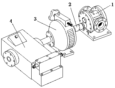
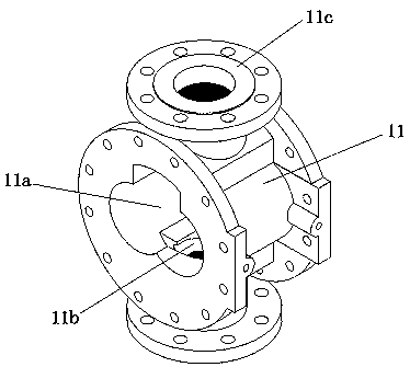
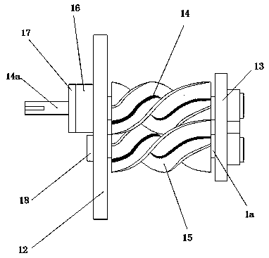
The invention discloses an environment-friendly water energy driving machine applied to a foam mixing pump. The water energy driving machine comprises a machine body housing, wherein a water energy power bin is arranged in the machine body housing; the water energy power bin penetrates through the two sides of the machine body housing; each penetrating opening is in an 8 shape; a main auger shaftand an auxiliary auger shaft are movably arranged in the water energy power bin; the main auger shaft and the auxiliary auger shaft are meshed side by side; the two sides of the machine body housing are fixedly provided with a first end cover and a second end cover through bolts correspondingly; two first through holes are formed in the first end cover, a first groove is formed in the second end cover; a shaft fixing base is embedded in the first groove; an 8-shaped convex block is cast and welded on the shaft fixing base; two second through holes are formed in the 8-shaped convex block side by side; and the two ends of the main auger shaft and the two ends of the auxiliary auger shaft are correspondingly inserted into the two first through holes and the two second through holes one by oneto be rotationally connected. According to the environment-friendly water energy driving machine, the working power of the foam mixing pump is effectively improved through the double-shaft synchronous rotation mode of the main auger shaft and the auxiliary auger shaft in a water turbine, and the water turbine is more convenient to install.

Description

technical field [0001] The invention mainly relates to the technical field of fire fighting equipment production, in particular to an environment-friendly water energy driving machine applied to a foam mixing pump. Background technique [0002] The most common fire extinguishing equipment in fire fighting equipment is foam fire extinguishing agent bottle. The production technology of foam fire extinguishing agent is mature, and it has the advantages of high output and low cost. It is one of the main products of fire fighting equipment manufacturers. [0003] In the production system of foam fire extinguishing agent, the foam according to a certain ratio is mixed with water through the foam mixing pump, and finally put into a container for storage. The driving mode used by the foam mixing pump includes motor drive or water turbine drive. Motor drive has the risk of high energy consumption and high cost, but the current hydraulic turbine drive is rarely used, because most of t...

Claims


Application Information

Patent Timeline
Patent Type & Authority Applications(China)
IPC IPC(8): F03C2/08
CPCF03C2/08
Inventor 郭跃新张良汪级龙
Owner WUHU SHIJI KAIXUAN FIRE EQUIP
Learn More