
Drying device capable of detecting moisture of textile based on principle of separation and reunion

A technology of drying device and detection device, applied in textile and papermaking, textile material processing, drying and other directions, can solve problems such as residual water droplets, damage to electronic components, and inability to quickly remove moisture from textile fabrics, so as to avoid damage. Effect

Inactive Publication Date: 2020-06-26
时兰兰
View PDF6 Cites 1 Cited by
  • Summary
  • Abstract
  • Description
  • Claims
  • Application Information

AI Technical Summary

Problems solved by technology

[0003] After the textile cloth is processed and cleaned, it is necessary to use a drying device to dry the textile cloth, but the existing drying device has the following problems when drying the textile cloth: 1. The moisture contained in the textile cloth cannot be quickly removed, If the textile fabric with high water content is put into the drying box, the water droplets on the textile fabric will leak during the drying process, and the water droplets will inevitably cause damage to the electronic components inside the drying box. Visually or tactilely feel the moisture content of textile fabrics. In this case, it is inevitable that the observation is not careful, and there is still the possibility of residual water droplets; 2. The existing drying boxes all use rollers for linear or U-shaped swing. Put the textile fabric, and dry the textile fabric through the drying steam above it. These devices are fixedly installed in the drying box, and cannot be moved and dried evenly according to actual needs, which often causes some textile fabrics to be overdried. Or the textile fabric is not dried, etc.

Method used

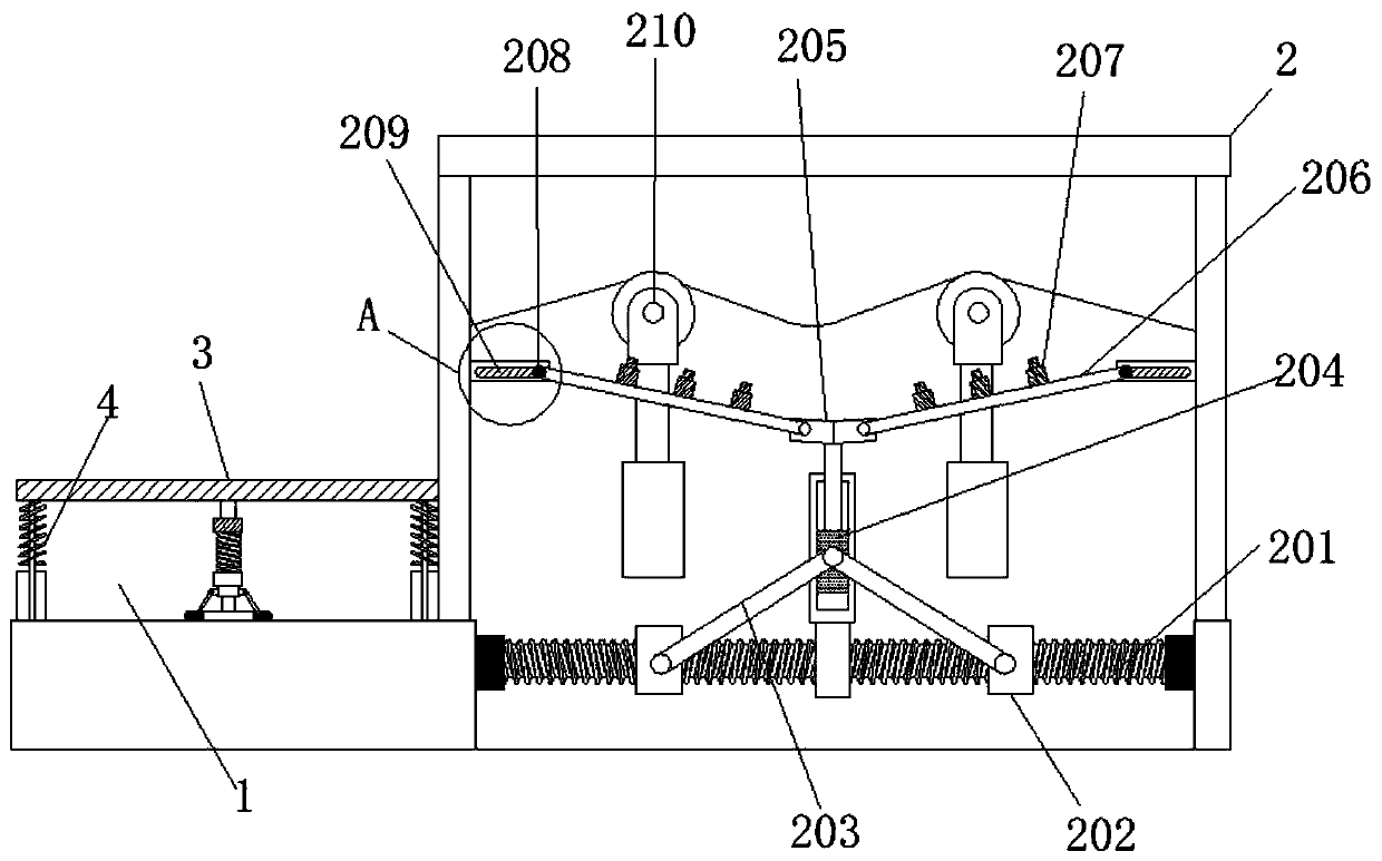

Image

  • Drying device capable of detecting moisture of textile based on principle of separation and reunion
  • Drying device capable of detecting moisture of textile based on principle of separation and reunion
  • Drying device capable of detecting moisture of textile based on principle of separation and reunion

Examples


Embodiment Construction

[0023] The following will clearly and completely describe the technical solutions in the embodiments of the present invention with reference to the accompanying drawings in the embodiments of the present invention. Obviously, the described embodiments are only some, not all, embodiments of the present invention. Based on the embodiments of the present invention, all other embodiments obtained by persons of ordinary skill in the art without making creative efforts belong to the protection scope of the present invention.

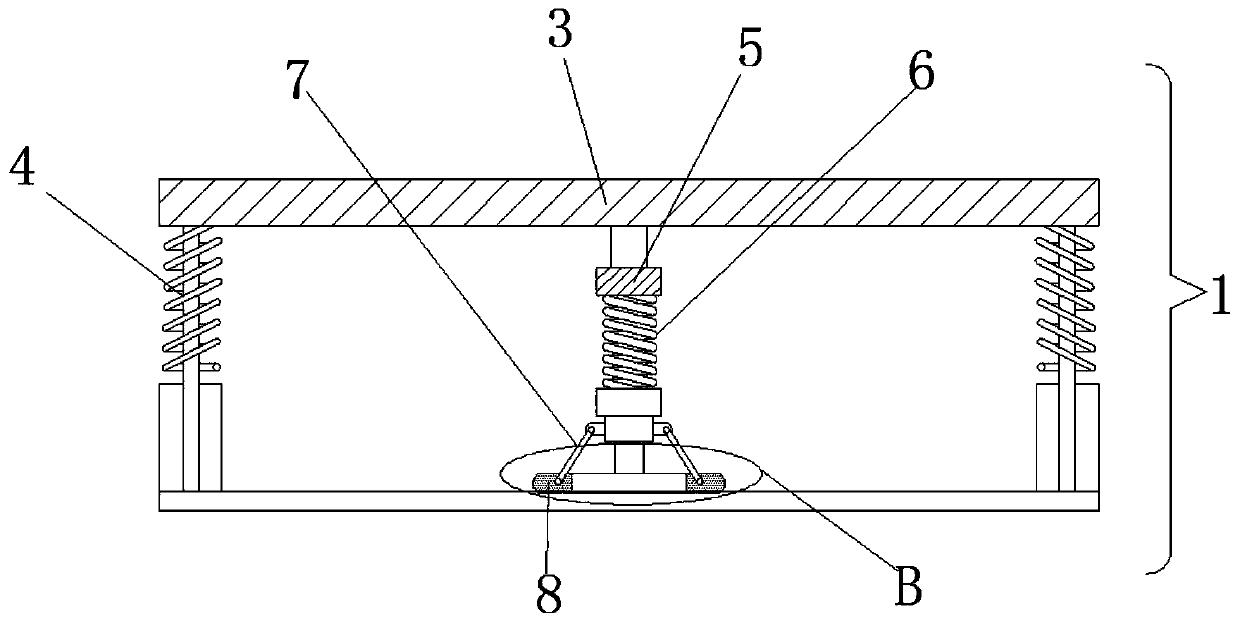
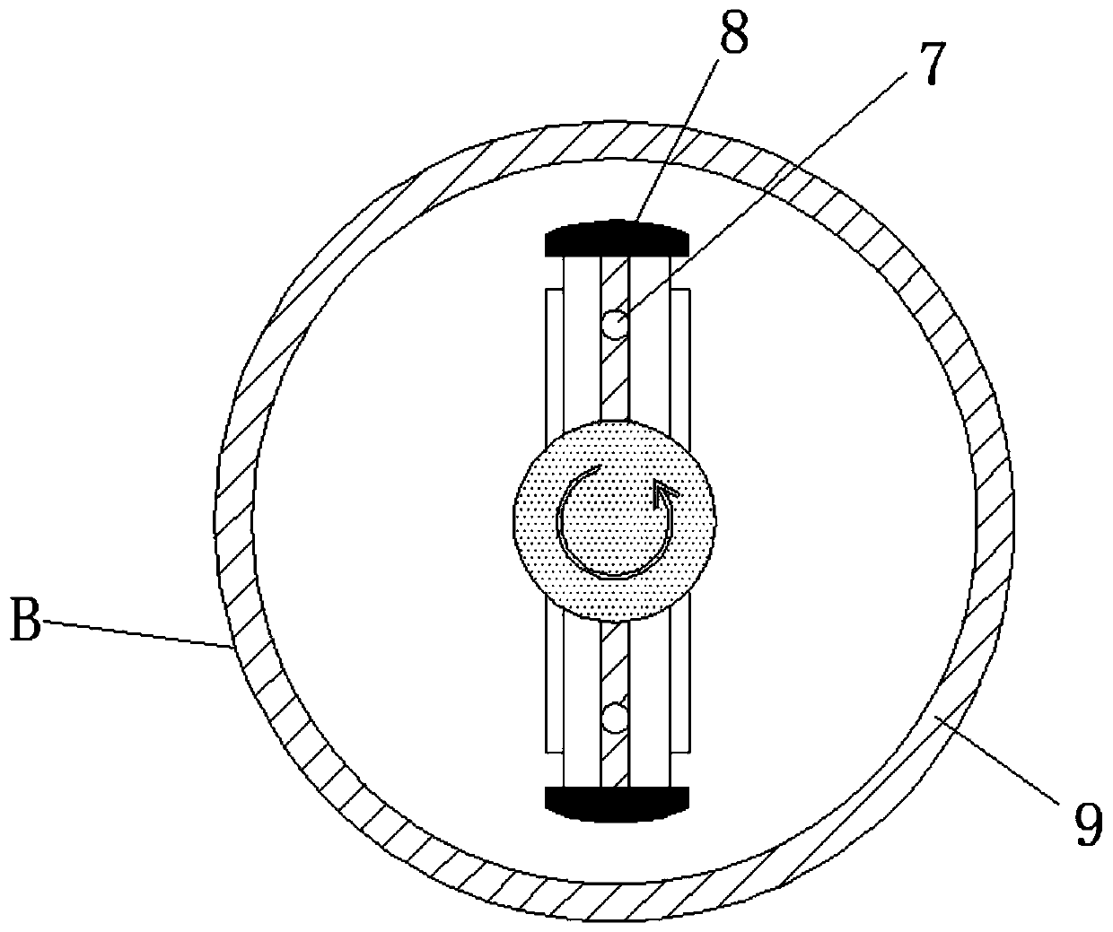
[0024] see Figure 1-6 , a drying device for detecting moisture in textiles based on the clutch principle, comprising a moisture detection device 1 and a drying device 2, a pressing platform 3 is arranged above the moisture detecting device 1, a pressing spring 4 is arranged below the pressing platform 3, and the pressing platform 3 is provided with a pressing column 5, the bottom of the pressing column 5 is connected with a buffer spring 6, the bottom end of ...


PUM


Abstract

The invention relates to the field of textile technology and discloses a drying device capable of detecting moisture of a textile based on the principle of separation and reunion. The drying device comprises a moisture detecting device and a drying device body, wherein a pressing platform is arranged above the moisture detecting device; a pressing spring is arranged below the pressing platform; athreaded rod is arranged at the bottom of the drying device body; a threaded block is connected onto the threaded rod in a sleeving manner; a connecting rod is arranged on the threaded block; a sliding block is connected onto the connecting rod; a hinge is arranged above the sliding block; a movable rod is connected onto the hinge; a steam device is placed on the movable rod; a movable fixture block is connected with one end of the movable rod; a movable sliding chute is formed in the external part of the movable fixture block; and a roller is arranged in the drying device body. According to the drying device, through cooperation of the structures, angle variation of the steam device is controlled, so that the purpose that the steam device uniformly dries the textile fabric is realized.

Description

technical field [0001] The invention relates to the technical field of textiles, in particular to a drying device for detecting moisture in textiles based on a clutch principle. Background technique [0002] Fabric is the material used to make clothing. As one of the three elements of clothing, fabric can not only interpret the style and characteristics of clothing, but also directly affect the color and shape of clothing. In the textile process, drying is essential In the link, only after drying the tie-dyed fabric can it be put into the later process. [0003] After the textile cloth is processed and cleaned, it is necessary to use a drying device to dry the textile cloth, but the existing drying device has the following problems when drying the textile cloth: 1. The moisture contained in the textile cloth cannot be quickly removed, If the textile fabric with high water content is put into the drying box, the water droplets on the textile fabric will leak during the dryin...

Claims


Application Information

Patent Timeline
Patent Type & Authority Applications(China)
IPC IPC(8): F26B5/08F26B13/08F26B13/14F26B21/00F26B25/00F26B25/22D06B15/00
CPCD06B15/00F26B5/08F26B13/08F26B13/14F26B21/005F26B25/00F26B25/22
Inventor 时兰兰
Owner 时兰兰
Learn More