
Over-current protection circuit based on output end of switching power supply

A technology of overcurrent protection circuit and switching power supply, which is applied to emergency protection circuit devices, output power conversion devices, electrical components, etc., and can solve problems such as damage to switching power supply circuits and limited ability to drive loads

Inactive Publication Date: 2020-06-26
GREE ELECTRIC APPLIANCES INC
View PDF3 Cites 0 Cited by
  • Summary
  • Abstract
  • Description
  • Claims
  • Application Information

AI Technical Summary

Problems solved by technology

[0002] There is no overcurrent protection circuit at the output end of the existing switching power supply circuit, because the ability of the output end of the switching power supply to drive the load is limited, so when the load driven by the output end of the switching power supply exceeds the preset load value when the switching power supply is designed, the switching power supply The current output at the output terminal will be greater than the maximum current allowed when designing the switching power supply, which usually leads to damage to the switching power supply circuit

Method used


Image

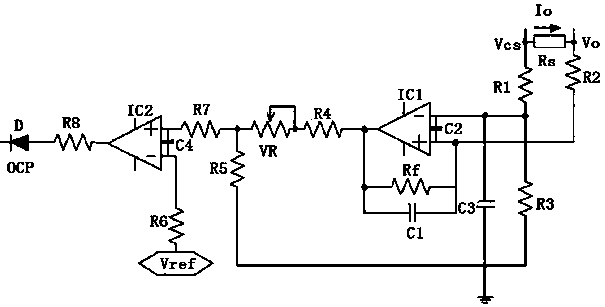
  • Over-current protection circuit based on output end of switching power supply

Examples


Embodiment Construction

[0019] In order to make the technical problems, technical solutions and beneficial effects to be solved by the present invention clearer, the present invention will be further described in detail below in conjunction with the accompanying drawings and embodiments. It should be understood that the specific embodiments described here are only used to explain the present invention, not to limit the present invention.

[0020] Attached below figure 1 The principles and structures of the present invention are described in detail with the embodiments.

[0021] The invention proposes an overcurrent protection circuit based on the output terminal of the switching power supply, which includes: a sampling circuit for collecting the current signal at the output terminal of the switching power supply, a voltage conversion circuit for converting the current signal into a voltage signal, and generating an overcurrent protection signal according to the voltage signal A comparison circuit, a...


PUM


Abstract

The invention discloses an over-current protection circuit based on the output end of a switching power supply. The over-current protection circuit comprises a sampling circuit used for collecting a current signal of the output end of the switching power supply, a voltage conversion circuit used for converting the current signal into a voltage signal, a comparison circuit used for generating an over-current protection signal according to the voltage signal, and a controller used for receiving the over-current protection signal, wherein the controller controls the working state of the switchingpower supply based on the over-current protection signal. The problem that the switching power supply is easily damaged due to current overload at the output end of the switching power supply is solved, and the operation safety of the switching power supply is improved.

Description

technical field [0001] The invention relates to the field of switching power supply, in particular to an overcurrent protection circuit based on the output terminal of the switching power supply. Background technique [0002] There is no overcurrent protection circuit at the output end of the existing switching power supply circuit, because the ability of the output end of the switching power supply to drive the load is limited, so when the load driven by the output end of the switching power supply exceeds the preset load value when the switching power supply is designed, the switching power supply The current output by the output terminal will be greater than the maximum current allowed when designing the switching power supply, which usually leads to damage to the switching power supply circuit. Contents of the invention [0003] In order to solve the technical problem that the switching power supply is easily damaged due to the current overload at the output terminal o...

Claims


Application Information

Patent Timeline
IPC IPC(8): H02H7/12H02M1/32
CPCH02H7/1203H02M1/32
Inventor 杨帆颜培炎伍玉行陈勇平金国义
Owner GREE ELECTRIC APPLIANCES INC
Learn More