Robot chassis and robot

A robot and chassis technology, applied in the field of children's education and entertainment robots, can solve the problems such as the inability to realize the free switching between the four-wheel chassis and the self-balancing chassis, and the single movement form of the robot chassis, and achieve simple and practical structure, simple structure, and compact space layout. Effect

Inactive Publication Date: 2020-06-30
SHENYANG SIASUN ROBOT & AUTOMATION
View PDF7 Cites 2 Cited by
  • Summary
  • Abstract
  • Description
  • Claims
  • Application Information

AI Technical Summary

Problems solved by technology

[0003] The present invention aims to overcome the defect that the existing robot chassis has a single movement form and cannot freely switch between the four-wheel chassis and the self-balancing chassis, and provides a switchable robot chassis and robot

Method used


Image

  • Robot chassis and robot
  • Robot chassis and robot
  • Robot chassis and robot

Examples


Embodiment 1

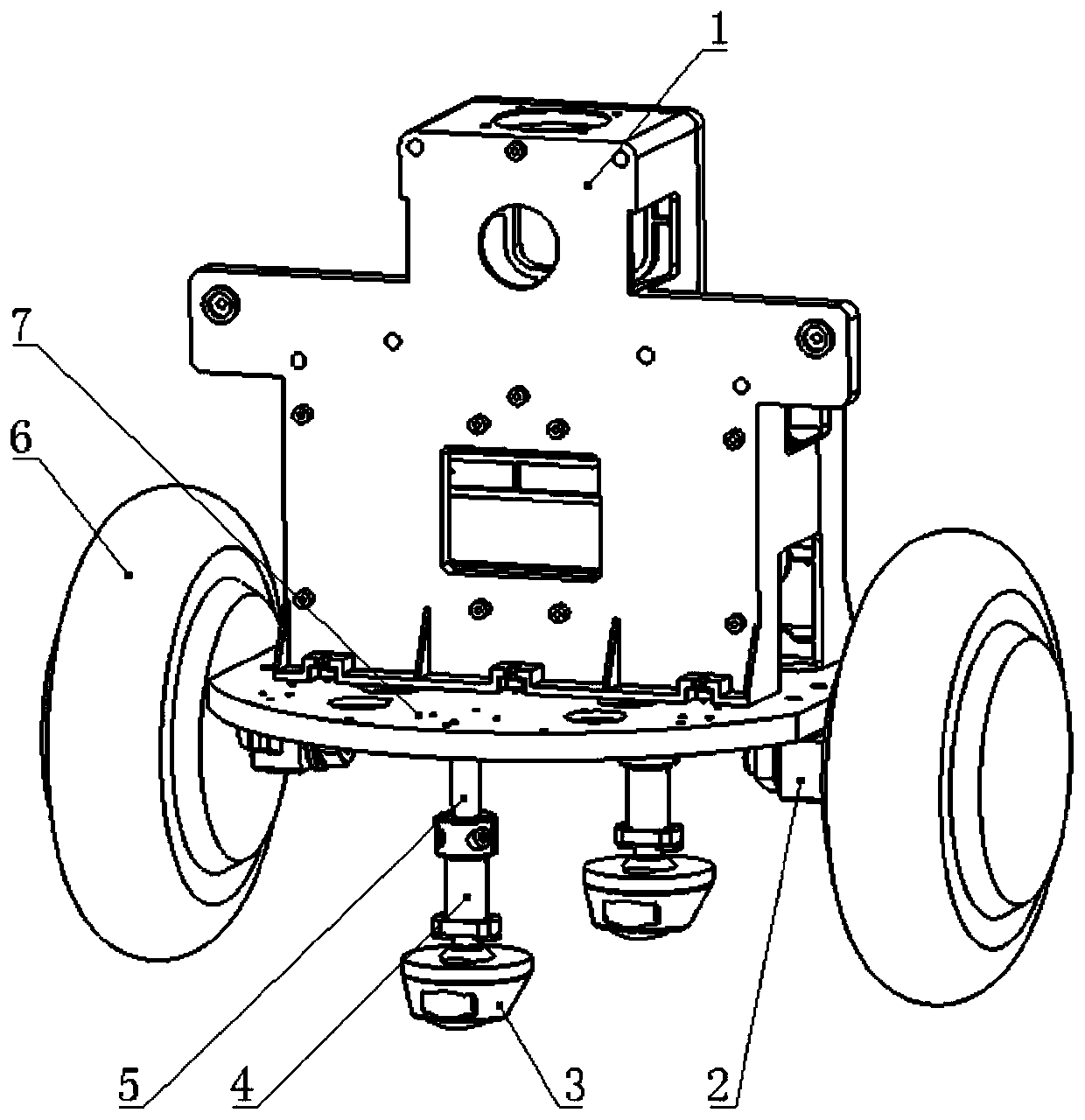
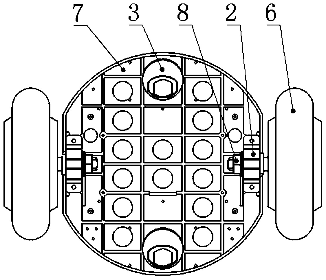
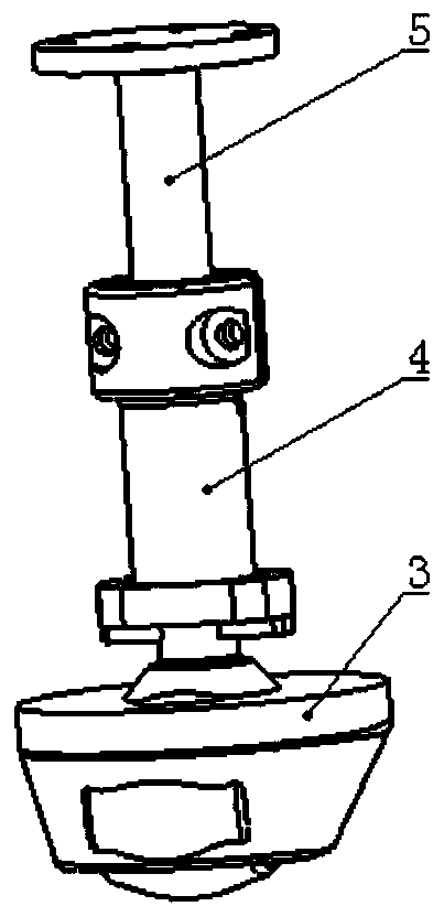
[0030] A robotic chassis such as Figure 1-2 As shown, it includes a chassis mounting plate 7, a pair of drive wheel mounts 2, a pair of drive wheels 6, a chassis switching device, and a universal wheel 3; the pair of drive wheel mounts 2 are symmetrically installed on the chassis. Both sides of the bottom of the plate 7; the central shafts of the pair of driving wheels 6 are respectively fixedly mounted on the driving wheel mounts 2; the central shafts of the driving wheels 6 are fixed on the driving wheel mounts 2 by threads . A locking nut 8 is arranged at the tail of the central shaft of the drive wheel.

[0031] The drive wheel 6 is fixed together with the drive wheel mounting seat 2 by threads, and the tail is locked with a lock nut 8 to prevent the drive wheel 6 from swinging left and right. There is a gap between the driving wheel mounts 2, and then they are fixed with pins, which can eliminate the hidden danger of the driving wheel 6 falling in motion. figure 2 sh...

Embodiment 2

[0043] A robot, comprising a robot trunk body and a chassis, the robot trunk body 1 is installed on the chassis mounting plate 7, the chassis is the robot chassis described in the above embodiment, the robot trunk body 1 The longitudinal centerline passes through the center of the chassis mounting plate 7 .

[0044] The robot torso main body 1 is installed on the chassis mounting plate 7 through screws and positioning pins.

[0045] The switching method of chassis of the present invention:

[0046] Such as figure 1 Shown is the working state of the four-wheel chassis. There is a driving wheel 6 on the left and right sides, and the bottom ends of the front and rear sides are universal wheels 3. The four wheels are in full contact with the ground during the robot's travel. When turning, the driving wheels on both sides Differential speed operation, the front and rear universal wheels follow the movement, ensuring stable and reliable operation.

[0047] If you need to use the ...


PUM


Abstract

The invention discloses a robot chassis which comprises a chassis mounting plate, a pair of driving wheel mounting seats, a pair of driving wheels, a chassis switching device and universal wheels. Thepair of driving wheel mounting seats are symmetrically arranged on two sides of the bottom of the chassis mounting plate; central shafts of the pair of driving wheels are fixedly mounted on the driving wheel mounting seats respectively; the chassis switching device is mounted on the chassis mounting plate, the longitudinal center line of the chassis switching device penetrates through the centerof the chassis mounting plate, and the center connecting lines of the chassis switching device and the two driving wheels are perpendicular to each other; and the universal wheels are arranged below the chassis switching device, and the chassis switching device can telescopically adjust the height of the universal wheels. The free switching of the motion mode between the four wheels and the self-balancing chassis is mainly achieved by manually adjusting the height of a free telescopic rod, the structure is simple and practical, the cost is low, the space layout is compact, driving wheel systems and universal wheel systems are both symmetrically arranged, the gravity center of a robot can be guaranteed to be in the center of motion, and the self-balancing motion is more facilitated.

Description

technical field [0001] The invention relates to the field of children's education and entertainment robots, and more specifically, to a robot with a switchable chassis. Background technique [0002] At present, due to the popularization of intelligence, people have put forward higher requirements for the working ability of children's educational and entertainment robots, not only requiring the robot to have a beautiful appearance and simple operation, but also require the characteristics of miniaturization, practicality, simplification, and modularization. The robot chassis carries multiple functions such as stability, movement, and positioning. The robot chassis is an important part of the robot, and is used to control the unit structure of the robot's forward, backward, and steering functions. Most existing robots use a fixed-moving chassis. Such a structure is similar to the fixed-moving chassis used by most robots. Such a structure is difficult to add other functions, an...

Claims


Application Information

Patent Timeline
Patent Type & Authority Applications(China)
IPC IPC(8): B25J5/00B25J9/00B62D57/02
CPCB25J5/00B25J9/00B62D57/02B25J5/007B25J9/0009
Inventor 王禹马壮赵鹏刘晓帆姜彬于海亮
Owner SHENYANG SIASUN ROBOT & AUTOMATION
Why Eureka
Try Eureka