Coating equipment for automobile door handle

A technology for covering equipment and door handles, applied in the field of auto parts processing equipment, can solve the problems of difficulty in guaranteeing the quality of covering, occupation of hands, discount on the service life of door handles, etc., to achieve efficient and comprehensive covering operations and reduce work Burden, good effect of covering operation

Active Publication Date: 2020-06-30
广州勒高汽车科技有限公司
View PDF12 Cites 0 Cited by
  • Summary
  • Abstract
  • Description
  • Claims
  • Application Information

AI Technical Summary

Problems solved by technology

[0002] Cars can improve the quality of life and make holiday travel more convenient. The door handle is an important component of the car door body. During the production and processing of the door handle, it is necessary to cover the door handle with a coating material, which requires a special car. The cladding equipment of the car door handle is assisted, but the traditional cladding equipment of the car door handle has many deficiencies, the operation is cumbersome, and more hands are occupied, so the cladding operation cannot be performed better, and the work burden of the personnel is virtually increased. It is unavoidable that the loosening will affect the coating process, and the efficient and comprehensive coating operation cannot be realized. The mecha

Method used


Image

  • Coating equipment for automobile door handle
  • Coating equipment for automobile door handle
  • Coating equipment for automobile door handle

Examples


Embodiment 1

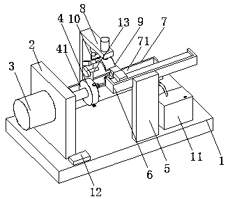
[0024]Embodiment 1: A coating device for a car door handle, including a bottom plate 1, a clamping mechanism 4, a coating fixture mechanism 6, an adjustment mechanism 7, a precise control baking mechanism 9, a cutting mechanism 10 and a maintenance mechanism 11, and the bottom plate 1 Provide support and installation place, the left side of the upper wall of the bottom plate 1 is provided with a vertical plate 2, the left wall of the vertical plate 2 is provided with a motor 3, the output shaft of the motor 3 is connected with the wall of the vertical plate 2 through bearings, and the motor 3 The output shaft of the vertical plate 2 extends to the right side of the vertical plate 2, and the motor 3 on the left wall of the vertical plate 2 runs, and then drives the clamped door handle to rotate and cover the operation. Connected, the clamping mechanism 4 is arranged on the right end of the output shaft of the motor 3, the cladding fixture mechanism 6 is arranged on the upper end...

Embodiment 2

[0027] The difference between this embodiment and Embodiment 1 is:

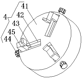
[0028] In this embodiment, the clamping mechanism 4 includes a rotating disk 41, a bar-shaped adjustment groove 42, a wire post 43, a knob 44, and a splint 45. The center of the left wall of the rotating disk 41 is fixedly connected to the right end of the output shaft of the motor 3. Two bar-shaped adjustment grooves 42 are equiangularly arranged on the right wall of the rotating disc 41, and the wire post 43 is rotatably connected with the inner wall of the bar-shaped adjustment groove 42 through a bearing, and the outer end of the wire post 43 extends to the bottom of the bar-shaped adjustment groove 42 The outside is provided with a knob 44 at the end, the support block at the left end of the splint 45 is threadedly connected with the wire column 43, the slider on the side wall of the support block at the left end of the splint 45 is slidingly connected with the inner wall chute of the bar-shaped adjustmen...

Embodiment 3

[0031] The difference between this embodiment and Embodiment 1 is:

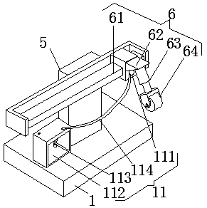
[0032] In this embodiment, the adjustment mechanism 7 includes a grooved plate 71, a rotating screw rod 72, an adjusting block 73 and an adjusting motor 74. The grooved plate 71 is arranged on the rear side of the upper wall of the bottom plate 1, and the two ends of the rotating screw rod 72 pass through the bearings. Rotately connected with the inner wall of the groove plate 71, the adjusting block 73 is threadedly connected with the rotating screw mandrel 72, the sliding plate on the side wall of the adjusting block 73 is slidingly connected with the inner wall chute of the groove plate 71, and the upper end surface of the adjusting block 73 is connected with the L-shaped The bottom end of the plate 8 is fixedly connected, the adjusting motor 74 is arranged on the left wall surface of the groove plate 71, the output shaft of the adjusting motor 74 is fixedly connected with the left end of the rotating screw...


PUM


Abstract

The invention discloses coating equipment for an automobile door handle. The coating equipment comprises a bottom plate, a clamping mechanism, a coating clamp mechanism, an adjusting mechanism, a finecontrol baking mechanism, a cutting mechanism and a curing mechanism. A vertical plate is arranged on the left side of the upper wall of the bottom plate, a motor is arranged on the left side wall ofthe vertical plate, an output shaft of the motor is connected with the wall body of the vertical plate in a rotating mode through a bearing, the output shaft of the motor extends to the right side ofthe vertical plate, a supporting plate is arranged on the front side of the upper wall of the bottom plate, the clamping mechanism is arranged at the right end of the output shaft of the motor, the coating clamp mechanism is arranged at the upper end of the rear wall of the supporting plate, the adjusting mechanism is arranged on the rear side of the upper wall of the bottom plate, and an L-shaped plate is arranged at the upper end of the adjusting mechanism. The coating equipment for the automobile door handle is easy to operate and can properly clamp and fix the door handle to achieve efficient and comprehensive coating work, mechanism design is reasonable, the consistency of all the mechanisms is good, the service life of the door handle is prolonged, and the coating quality is ensured.

Description

technical field [0001] The invention relates to the technical field of auto parts processing equipment, in particular to a coating equipment for an automobile door handle. Background technique [0002] Cars can improve the quality of life and make holiday travel more convenient. The door handle is an important component of the car door body. During the production and processing of the door handle, it is necessary to cover the door handle with a coating material, which requires a special car. The cladding equipment of the car door handle is assisted, but the traditional cladding equipment of the car door handle has many deficiencies, the operation is cumbersome, and more hands are occupied, so the cladding operation cannot be performed better, and the work burden of the personnel is virtually increased. It is unavoidable that the loosening will affect the coating process, and the efficient and comprehensive coating operation cannot be realized. The mechanism design is not rea...

Claims


Application Information

Patent Timeline
IPC IPC(8): B29C65/74B29C65/10B29C65/78B29L31/30
CPCB29C65/74B29C65/10B29C65/7841B29C66/0326B29C66/032B29C66/9141B29L2031/3029
Inventor 黄克伟
Owner 广州勒高汽车科技有限公司
Why Eureka
Try Eureka