Impact response modeling method for composite laminated plate
A composite material layer and modeling method technology, which is applied in the field of impact response modeling of composite material laminates, can solve the problems of damage process monitoring, dynamic response of laminated structures and complex failure process, and achieve the effect of improving accuracy
- Summary
- Abstract
- Description
- Claims
- Application Information
AI Technical Summary
Problems solved by technology
Method used
Image
Examples
Embodiment 1
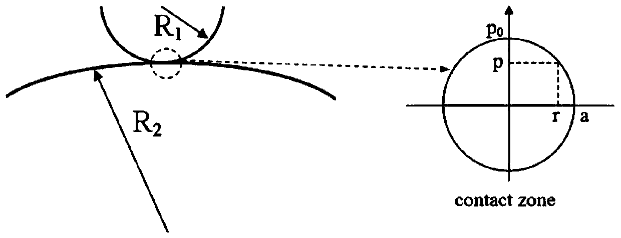
[0051]In this embodiment, a method for modeling the impact response of a composite laminate is provided, and the impact response of the composite laminate is analyzed by using the smoothed particle dynamics (Smoothed Particle Hydrodynamics, SPH) method. The modeling method includes the following steps:
[0052] Step 1: Calculate the Hertz contact stiffness k according to formula (1) c :
[0053]
[0054] Among them, R p ,E p and v p Respectively represent the punch radius, elastic modulus and Poisson's ratio, E T Indicates the modulus of elasticity of the outermost plate of the composite material laminate along the thickness direction;
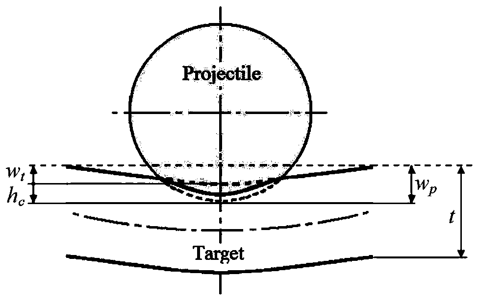
[0055] Step 2: Obtain the indentation depth h of the composite material laminate c , and calculate the contact load F between the composite laminate and the impactor according to formula (2) imp :
[0056]
[0057] Step 3: according to formula (3) and (4), utilize the smooth particle dynamics SPH discretization method of Lagrangi...
Embodiment 2
[0087] This embodiment provides a method for modeling the impact response of a composite material laminate, wherein the composite material laminate is a square carbon fiber reinforced epoxy resin composite material laminate supported on four sides, and the impact object is a rigid ball, and the two collide. The relevant information of the punch and the laminate is shown in Table 2.1:
[0088] Table 2.1 Geometric dimensions and material parameters of punches and laminates
[0089]
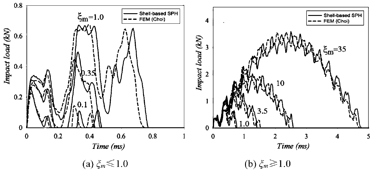
[0090]In this embodiment, the laminate is a bounded flat plate. During impact contact, the shock wave encounters the boundary and is bounced back, which can be classified as a boundary-controlled shock problem. The high-order oscillations in the impact load history cannot be obtained with the infinite plate model, so this embodiment uses the finite element solution results for comparison. In the SPH model, 1 / 4 of the neutral plane is discretized into 26×26 particles, and the modeling method of ...
Embodiment 3
[0103] In this embodiment, a method for modeling the impact response of a composite laminate is provided, wherein the composite laminate is a carbon fiber double-horse resin composite laminate simply supported on four sides, and the impact object is a pointed punch. collision. The shapes and material properties of laminates and punches are given in Table 3.1.
[0104] Table 3.1 Geometric dimensions and material parameters of punches and laminates
[0105]
[0106] The finite element method uses 4-node, 48-degree-of-freedom hyperbolic quadrilateral shell elements. In this example, 16×16, 21×21, 26×26 and 41×41 SPH shell particles are respectively used to discrete the 1 / 4 neutral plane, and the geometric nonlinear SPH modeling method is used to analyze and calculate the impact damage and position. Figure 6 It is a schematic diagram of the impact damage outline and location, in which, the internal damage caused by the impact of composite laminates is obtained by ultrasonic ...
PUM
 Abstract
Description
Claims
Application Information
 - R&D
- Intellectual Property
- Life Sciences
- Materials
- Tech Scout
- Unparalleled Data Quality
- Higher Quality Content
- 60% Fewer Hallucinations
Browse by: Latest US Patents, China's latest patents, Technical Efficacy Thesaurus, Application Domain, Technology Topic, Popular Technical Reports.
© 2025 PatSnap. All rights reserved.Legal|Privacy policy|Modern Slavery Act Transparency Statement|Sitemap|About US| Contact US: help@patsnap.com


