Glass substrate
A glass substrate and main surface technology, applied in glass molding, glass molding, glass manufacturing equipment, etc., can solve the problems of glass substrate damage, easy adhesion of glass substrates, etc., and achieve low-cost effects
- Summary
- Abstract
- Description
- Claims
- Application Information
AI Technical Summary
Problems solved by technology
Method used
Image

Examples
no. 1 approach 》
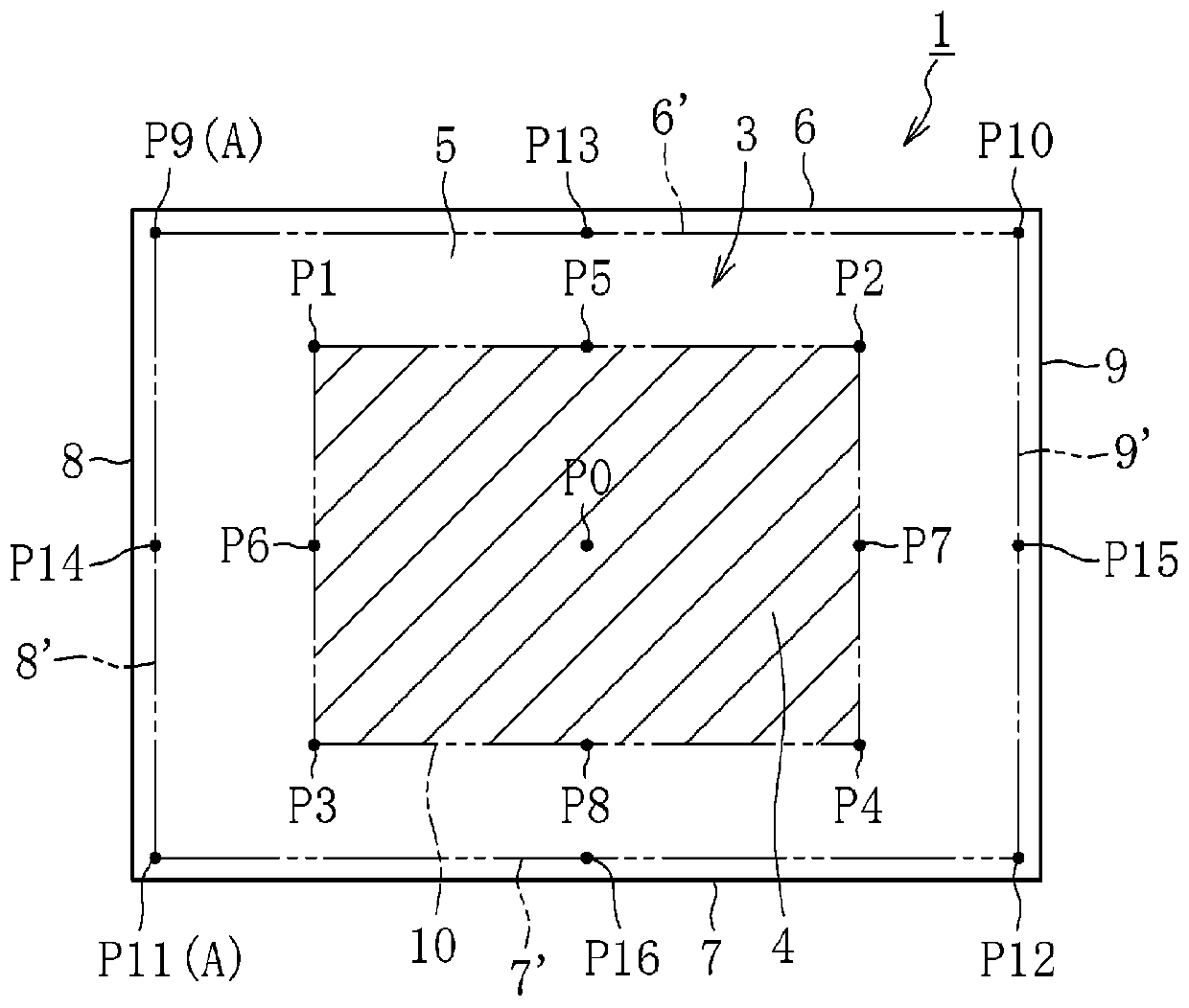
[0033] Below, refer to Figure 1 ~ Figure 3 A first embodiment of the present invention will be described.
[0034] Such as figure 1As shown, the glass substrate 1 of the present embodiment is formed in a rectangular shape, and is formed of, for example, silicate glass, silica glass, or the like, preferably borosilicate glass, and more preferably alkali-free glass. In this case, as an example of the glass composition of the glass substrate 1, it is possible to include SiO by mass %. 2 : 50%~70%, Al 2 o 3 : 12% to 25%, B 2 o 3 : 0%-12%, MgO: 0%-8%, CaO: 0%-15%, SrO: 0%-12%, BaO: 0%-15%.
[0035] In addition, the alkali-free glass mentioned here means the glass which does not contain an alkali component (alkali metal oxide) substantially, Specifically, it means the glass whose alkali component is 3000 ppm or less. From the viewpoint of at least preventing or reducing deterioration over time, glass with an alkali component of 1000 ppm or less is preferable, glass with an a...
no. 2 approach 》
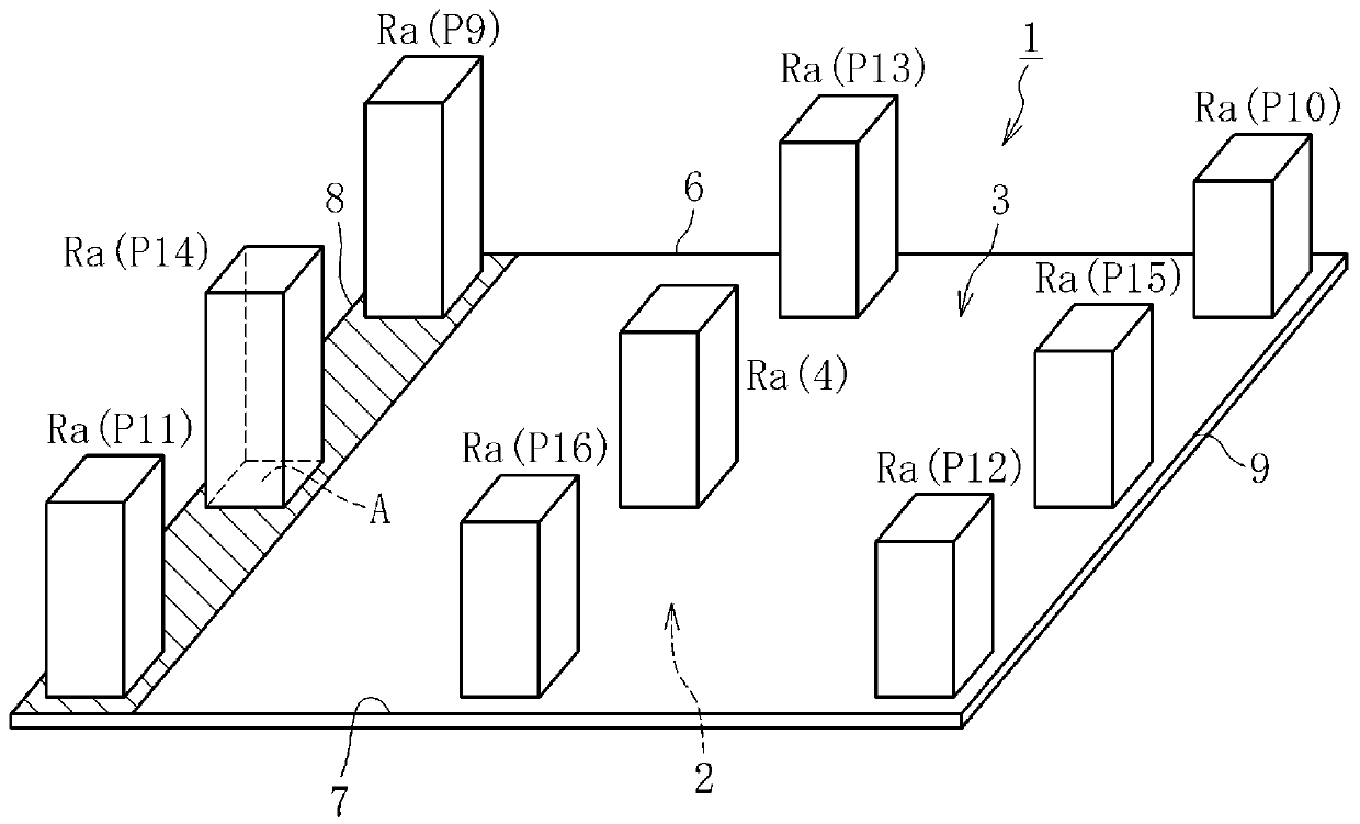
[0060] Figure 4 An example of the distribution of surface roughness Ra of the second main surface 3 of the glass substrate 1 according to the second embodiment of the present invention is shown. Figure 4 , the height of the histogram indicates the size of the surface roughness Ra, and the numbers or symbols in parentheses described above or on the side of the histogram respectively indicate figure 1 The position on the second main surface 3 of the glass substrate 1 shown in . Such as Figure 4 As shown, in the present embodiment, also in the outer peripheral region 5 of the second main surface 3, a surface roughened region A having a surface roughness Ra greater than the surface roughness Ra of the central region 4 by 0.2 nm or more is provided. .
[0061] In addition, in this embodiment, in addition to the above configuration, the surface roughness region A extends along the long side portion 7 and the surface roughness Ra of the outer peripheral region 5 decreases as th...
no. 3 approach 》
[0070] Figure 6 An example of the distribution of surface roughness Ra of the second main surface 3 of the glass substrate 1 according to the third embodiment of the present invention is shown. Figure 6 , the height of the histogram indicates the size of the surface roughness Ra, and the numbers or symbols in parentheses described above or on the side of the histogram respectively indicate figure 1 The position on the second main surface 3 of the glass substrate 1 shown in . Such as Figure 6 As shown, in the present embodiment, also in the outer peripheral region 5 of the second main surface 3, a surface roughened region A having a surface roughness Ra greater than the surface roughness Ra of the central region 4 by 0.2 nm or more is provided. .
[0071] In addition, in the present embodiment, the surface-roughened region A is provided at one of the four corners defining the second main surface 3 . "Roughened surface area A is provided at the corner" refers to the surfa...
PUM
| Property | Measurement | Unit |
|---|---|---|
| surface roughness | aaaaa | aaaaa |
| surface roughness | aaaaa | aaaaa |
| surface roughness | aaaaa | aaaaa |
Abstract
Description
Claims
Application Information
 - R&D
- Intellectual Property
- Life Sciences
- Materials
- Tech Scout
- Unparalleled Data Quality
- Higher Quality Content
- 60% Fewer Hallucinations
Browse by: Latest US Patents, China's latest patents, Technical Efficacy Thesaurus, Application Domain, Technology Topic, Popular Technical Reports.
© 2025 PatSnap. All rights reserved.Legal|Privacy policy|Modern Slavery Act Transparency Statement|Sitemap|About US| Contact US: help@patsnap.com