High-pressure washing machine and high-pressure washing system

A technology of high-pressure cleaners and pressurized chambers, which is applied to mechanical equipment, machines/engines, cleaning methods and appliances, etc., which can solve problems such as unfavorable heat dissipation, and achieve the effects of improving cleaning effects, using convenience, and improving flexibility

Pending Publication Date: 2020-07-03
苏州贝米科技有限公司
View PDF0 Cites 0 Cited by
  • Summary
  • Abstract
  • Description
  • Claims
  • Application Information

AI Technical Summary

Problems solved by technology

[0004] At the same time, due to the existence of rapid sliding friction, a large amount of heat will be generated between the piston and the guide structure, which is obviously unfavorable for the heat dissipation in the entire device

Method used


Image

  • High-pressure washing machine and high-pressure washing system
  • High-pressure washing machine and high-pressure washing system
  • High-pressure washing machine and high-pressure washing system

Examples


Embodiment 1

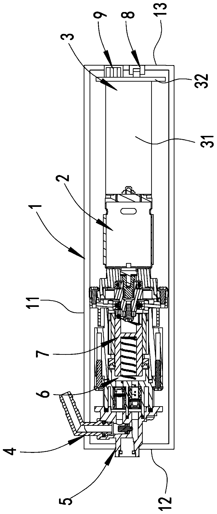
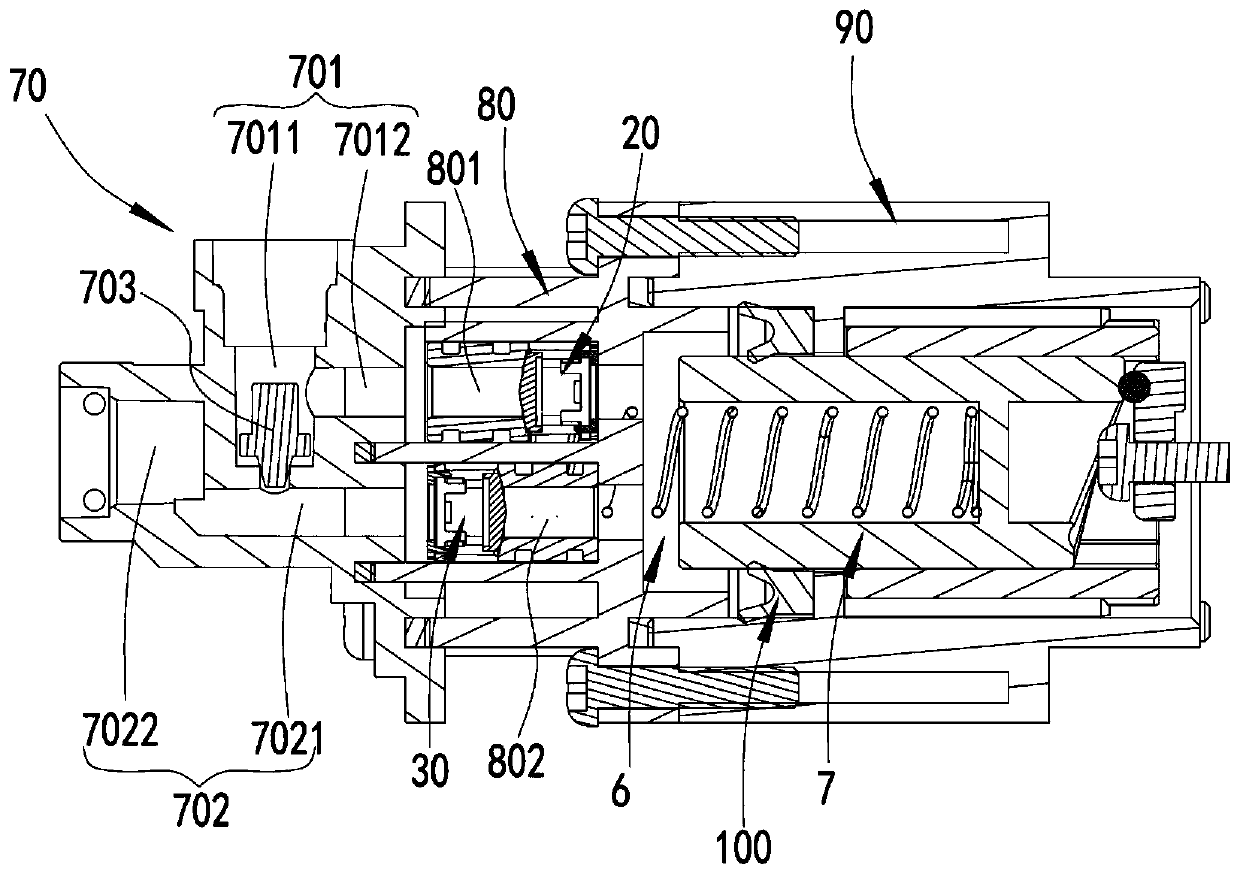
[0052] As attached figure 1 , Attached figure 2 As shown, the fluid inlet 4 and the fluid outlet 5 are connected to a fluid in and out control mechanism located in the housing 1. The fluid in and out control mechanism is preferably close to the front end of the housing 1. The fluid in and out control mechanism is located in the piston 7 When moving from the far end (when the user uses the end that the whole device points to the front) to the proximal end (when the user uses the end the whole device points to the rear) (when sucking), only allow external fluid to be sucked from the fluid inlet 4 In the pressurized chamber 6, the fluid in the pressurized chamber 6 cannot be discharged through the fluid outlet 5; and when the piston 7 moves from the proximal end to the distal end (when squeezing), no external fluid is allowed to pass through the fluid inlet 4 is sucked into the pressurized chamber 6, and only the fluid in the pressurized chamber 6 is allowed to be discharged thro...

Embodiment 2

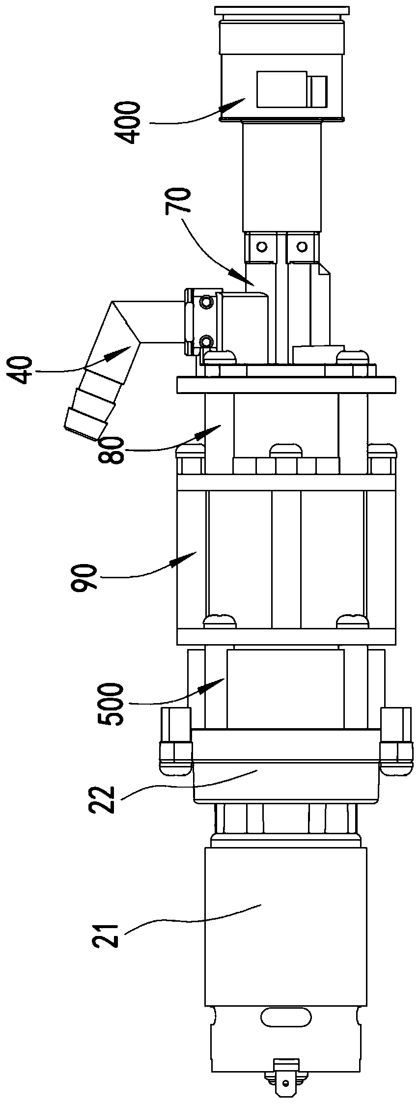
[0064] The difference between this embodiment and the above-mentioned embodiment 1 is as follows: Figure 5 As shown, the fluid inlet 4 is provided at the proximal end of the housing 1, preferably at the proximal end surface, that is, the fluid inlet 4 includes at least one hole on the end panel 13 at the proximal end of the housing. At this time, because there is a relatively large distance between the fluid inlet 4 and the distal fluid in and out control mechanism, a fluid channel 300 is also provided between the fluid inlet 4 and the inlet of the fluid in and out control mechanism, and the fluid The channel 300 is preferably arranged inside the housing 1, of course, it can also be arranged outside the housing 1 in other embodiments.

[0065] At this time, the fluid inlet 4 can also extend a certain distance vertically outward from the proximal end panel 13 of the housing 1, so as to facilitate the detachable connection with the pipe joint 40 or an external pipe. Of course, the...


PUM


Abstract

The invention discloses a high-pressure washing machine and a high-pressure washing system. The high-pressure washing machine comprises a shell, a driving structure, a circuit structure, a fluid inlet, a fluid outlet, a fluid inlet and outlet control mechanism for allowing fluid to enter a pressurizing cavity only from the fluid inlet and be discharged from the fluid outlet, and a piston which isdriven by the driving structure to reciprocate linearly so as to lead the fluid into the pressurizing cavity from the fluid inlet and discharge the fluid from the fluid outlet after being pressurized,wherein an anti-rotation structure for limiting the rotation of the piston is arranged between the piston and a surface arranged surrounding the periphery of the piston, and the anti-rotation structure enables the piston to be in rolling connection with the surface arranged surrounding the periphery of the piston. According to the scheme, a rolling connection mode is adopted, on the one hand, thefriction force between the piston and the shell or a straight cylinder is reduced, the abrasion and heat generation among components are reduced, and the service life is prolonged; and on the other hand, the rotation of the piston can be sufficiently limited by the sliding of a rolling ball or a rolling pin in a guide groove, so that the interference of the rotation of the piston to the driving structure is avoided, and the driving reliability and stability are effectively ensured.

Description

Technical field [0001] The invention relates to cleaning equipment, especially a high-pressure cleaning machine and a high-pressure cleaning system. Background technique [0002] A high-pressure cleaner is a device that uses a reciprocating piston to compress the liquid in the cylinder to form a high-pressure water stream to clean objects. It can be used to clean cars, floors, walls, doors and windows, etc. With the continuous improvement of people's living standards, high-pressure cleaners are also favored by more and more families. [0003] Since the piston needs to expand and contract in a straight line, in order to ensure that it can move in a straight line, a certain guiding structure surrounding the outer circumference of the piston is usually set to limit the axial position of the piston, and there is bound to be a gap between the outer wall of the piston and the guiding structure. There is a large amount of sliding friction. Due to long-term sliding friction, the surface o...

Claims


Application Information

Patent Timeline
Patent Type & Authority Applications(China)
IPC IPC(8): B08B3/02B08B13/00F04B53/00F04B53/16F04B53/14F04B17/03F04B1/14F04B1/12
CPCB08B3/026B08B13/00B08B2203/0217B08B2203/0223B08B2203/027B08B2203/0282F04B1/124F04B1/14F04B1/145F04B17/03F04B53/00F04B53/14F04B53/16
Inventor 刘良兵赵殿虎
Owner 苏州贝米科技有限公司
Why Eureka
Try Eureka