Double-end saw cutting machine with automatic locating function

A sawing machine and automatic positioning technology, which is applied to metal sawing equipment, sawing machine devices, manufacturing tools, etc., can solve the problems of large error fluctuation, low efficiency, and easy misreading, and achieve the effect of improving efficiency and accurate positioning.

Pending Publication Date: 2020-07-03
湖南金立星机械科技有限公司
View PDF0 Cites 0 Cited by
  • Summary
  • Abstract
  • Description
  • Claims
  • Application Information

AI Technical Summary

Problems solved by technology

Since the output shaft of the saw blade drive motor does not have the ability to directly install the saw blade, it is necessary to set up a saw blade installation shaft and a saw blade bearing to install the saw blade. Therefore, a pulley and a belt are also required for transmission. In order to prevent the belt from loosening due to stretching, It is necessary to adjust the distance between the saw blade drive motor and the saw blade installation axis by adjusting the position of the saw blade drive motor, resulting in complex structure of the cutting assembly, high production cost, easy failure, and low reliability
Belt transmission is adopted, the transmission efficiency is low, which is not conducive to energy saving and environmental protection
Moreover, for relatively long profile workpieces, the carrying capacity of the bracket is limited and cannot fully support the profile workpieces
[0003] In addition, when the existing double-headed saws process profile workpieces, it is usually necessary to cut the profile workpieces at 45°, 60° or 90°, which requires not only manual on-site measurement of various data but also manual adjustment of the fixed cutting unit , the distance of the active cutting unit is not only inefficient but also unreliable
The measurement is cumbersome and the error fluctuates greatly; the work efficiency is low, the reading is not intuitive, and when the light is insufficient, it is easy to cause misreading, resulting in processing waste, which is not conducive to energy saving and environmental protection

Method used


Image

  • Double-end saw cutting machine with automatic locating function
  • Double-end saw cutting machine with automatic locating function
  • Double-end saw cutting machine with automatic locating function

Examples


Embodiment Construction

[0058] The present invention and its beneficial technical effects will be described in further detail below in conjunction with the accompanying drawings and preferred implementation methods. The descriptions of orientation and position in the text are only relative positions for convenience of description, not absolute positions.

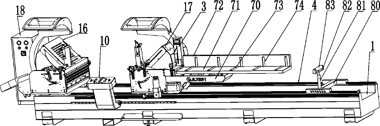
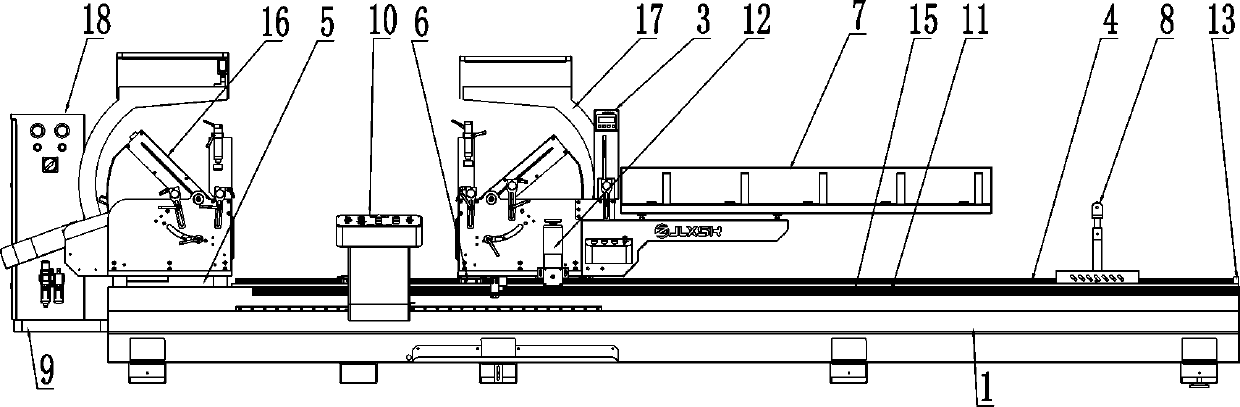
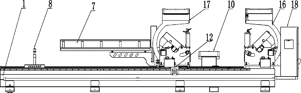
[0059] see Figure 1 to Figure 4 , a double-head saw cutting machine assembly, which includes a horizontal frame 1 arranged longitudinally extending from left to right, 2 sets of saw blade cutting units 2, a material height measuring device 3, and a horizontal frame arranged on the horizontal frame 1 2 linear horizontal rails 4, fixed seat 5, sliding seat 6, material support frame 7, movable material rack 8, electric cabinet frame 9, control box 10, automatic controller, transmission frame 11, drive the sliding seat 6 to slide and receive Controlled by the driving device 12 of the automatic controller. Wherein the automatic controller (also known ...


PUM


Abstract

A double-end saw cutting machine with an automatic locating function comprises a horizontal rack arranged in a manner of extending in the left-and-right longitudinal direction, a fixed cutting unit fixedly arranged on the horizontal rack, a movable cutting unit movably arranged on the horizontal rack in the left-and-right longitudinal direction and an automatic controller. The fixed cutting unit and the movable cutting unit comprise metal round saw blades used for sawing correspondingly and are used for being controlled by the automatic controller to cut cut profiles through the metal round saw blades. The double-end saw cutting machine has the advantages that the cutting angles, lengths, heights and other parameter data of the cut profiles can be acquired through a data sampling device, and therefore the automatic controller can achieve automatic distance control and cut profile length control according to the parameter data, operation is automatically completed, efficiency is improved, and locating is accurate.

Description

technical field [0001] The invention relates to a cutting machine, in particular to a double-head saw cutting machine with automatic positioning function. Background technique [0002] Profile workpieces often need to cut at least one end, generally both ends are cut at the same time, such as door and window profile workpieces need to be cut at both ends at right angles or 45 degree angles, etc. In order to improve the processing speed of profile workpieces, double-head cutting is often used Saw cutting machine, the existing double-head saw cutting machine includes a frame, and a fixed cutting unit, a movable cutting unit, a slide rail, and a support frame arranged on the frame; the movable cutting unit is slidably arranged on the slide rail, The support frame moves together with the active cutting unit. Both the fixed cutting unit and the movable cutting unit include a saw blade drive motor, a guide mount, a saw blade installation shaft, a saw blade bearing, a saw blade, a...

Claims


Application Information

Patent Timeline
Patent Type & Authority Applications(China)
IPC IPC(8): B23D45/02B23D45/10B23D45/14B23D47/00B23D47/04B23D47/10B23D47/12B23D59/00
CPCB23D45/024B23D45/10B23D45/143B23D47/00B23D47/04B23D47/10B23D47/12B23D59/00B23D59/001B23D59/006
Inventor 唐明星
Owner 湖南金立星机械科技有限公司
Why Eureka
Try Eureka