Pipeline welding robot integrating functions of TIG welding and MIG welding

A technology for welding robots and pipes, which is applied in the direction of welding equipment, welding accessories, welding rod characteristics, etc., can solve the problems of reducing welding accuracy, large height and volume of crawling units, and affecting welding quality, and achieve height and volume reduction, which is conducive to welding Accuracy, overall small form factor effect

Pending Publication Date: 2020-07-03
TIANJIN HUAYOU PETRO CHEM ENG CO LTD
View PDF5 Cites 2 Cited by
  • Summary
  • Abstract
  • Description
  • Claims
  • Application Information

AI Technical Summary

Problems solved by technology

[0004] In the traditional pipeline welding robot structure, either the relevant structure of TIG welding or the relevant structure of MIG welding is set, but the two structures are not organically combined, which causes the operator to change the welding method as a whole. Pipeline welding robot reduces production efficiency and increases labor intensity of welders
Moreover, the structural adjustment structure of the swing adjustment unit in the existing pipeline welding robot is too simple to achieve complex position adjustment, which also reduces the welding accuracy and affects the welding quality
In addition, the traveling module and the driving module in the existing crawling unit are relatively large in size, resulting in the overall height and volume of the crawling unit being too large. When the gap between the pipelines is small, the crawling unit will bump into the adjacent pipeline, resulting in abnormal complete welding work
[0005] After searching, there is no relevant literature on the organic integration of TIG welding structure and MIG welding structure. Therefore, a solution that can effectively solve the problems existing in the existing technology is urgently needed

Method used


Image

  • Pipeline welding robot integrating functions of TIG welding and MIG welding
  • Pipeline welding robot integrating functions of TIG welding and MIG welding
  • Pipeline welding robot integrating functions of TIG welding and MIG welding

Examples


Embodiment Construction

[0050] Below in conjunction with the examples, the present invention is further described, the following examples are illustrative, not limiting, and the protection scope of the present invention cannot be limited by the following examples.

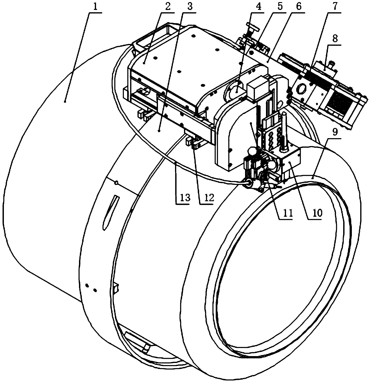
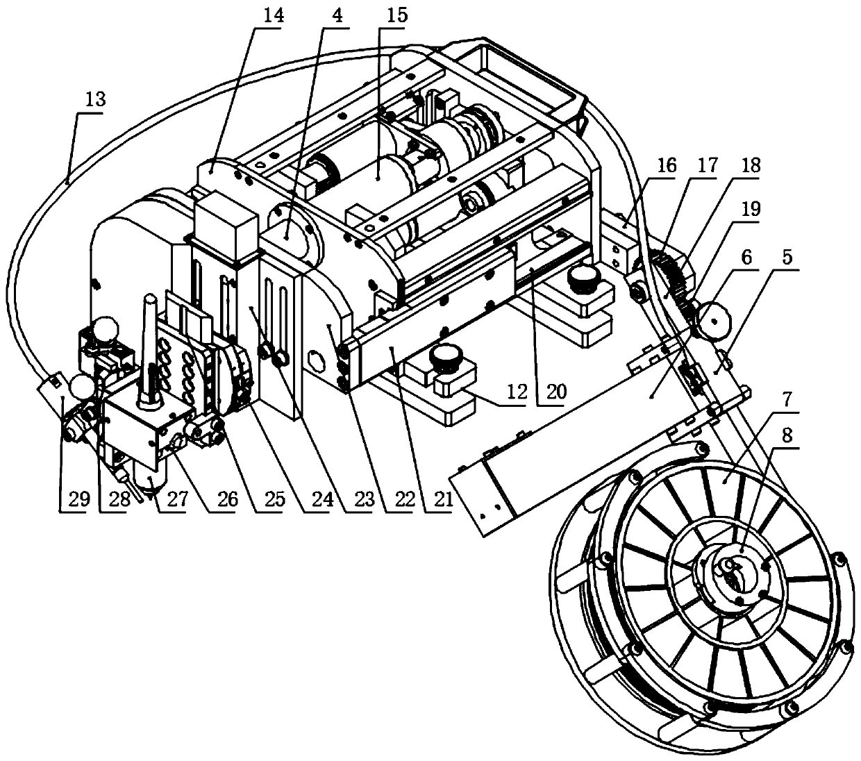
[0051] A pipeline welding robot integrating TIG welding and MIG welding functions, such as Figure 1-7 As shown, it includes a crawling unit 2, a wire reel unit, a position adjustment unit 11 and a welding unit 10. The wire reel unit is arranged on the crawler unit and is used to transport welding wire 46. The crawler unit drives the welding unit along the axial direction of the pipeline 1 through the position adjustment unit. The direction reciprocates at the welding seam 9. The innovation of the present invention is that the welding unit includes a base, a nozzle 27 and a welding wire. Weld and spray inert gas.

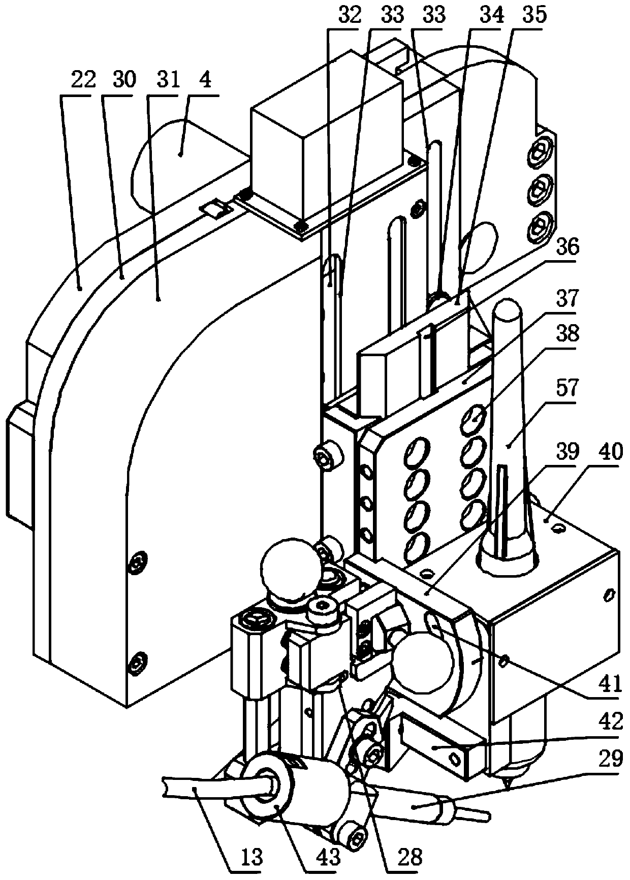
[0052] When the base is in the Figure 1~6 Tungsten pole 57 is set as shown and welding wire ( Figure 4 When the end of m...


PUM


Abstract

The invention relates to a pipeline welding robot integrating functions of TIG welding and MIG welding. A welding unit comprises a pedestal, a nozzle and a welding stick, wherein the pedestal is arranged at the front end of a position adjusting unit, the nozzle is arranged on the pedestal, and an air outlet of the nozzle faces a weld joint of the pipeline and sprays inert gas. TIG welding and MIGwelding can be transformed conveniently and flexibly, so that the fitness of the whole robot is improved, the labor intensity of a welder is reduced and the welding work efficiency is improved. In addition, the whole robot can be suitable for welding pipelines of different wall thicknesses by means of multi-stage adjustment in all the direction. The optimum relative positions can be kept between atungsten electrode or the welding stick and the weld joint. Furthermore, the height and volume of the whole robot are reduced by means of flatted improvement and adjustment of adhesion of a wire reelunit, so that the robot is suitable for finishing welding work in a scene where the separation distance between pipelines is relatively small.

Description

technical field [0001] The invention belongs to the technical field of welding robot structure improvement, in particular to a pipeline welding robot integrating TIG welding and MIG welding functions. Background technique [0002] Pipeline welding robot is also called pipeline automatic welding machine. It is an automatic welding equipment in industrial pipeline processing. It can replace manual welding by welders. It has the advantages of stable welding quality, improved working conditions for welders, and increased production efficiency. The structure of the pipeline welding robot is: including a crawling unit 2, a welding wire reel unit, a position adjustment unit 11 and a welding unit 10, the welding wire reel unit is arranged on the crawling unit, and the crawling unit is used to follow the The radial direction of the pipe runs, and the position adjustment unit drives the welding unit to reciprocate at the weld along the axial direction of the pipe. At the same time, t...

Claims


Application Information

Patent Timeline
Patent Type & Authority Applications(China)
IPC IPC(8): B23K9/167B23K9/173B23K9/133B23K9/28B23K9/32B23K101/06
CPCB23K9/167B23K9/173B23K9/133B23K9/287B23K9/325B23K2101/06
Inventor 薛晋澎
Owner TIANJIN HUAYOU PETRO CHEM ENG CO LTD
Why Eureka
Try Eureka