A horizontal installation device for a cantilever power system for an unmanned aerial vehicle

A technology of a power system and an installation device, which is applied in the field of horizontal installation devices of a cantilever power system for unmanned aerial vehicles, can solve the problems of affecting the flight operation, the horizontal offset of the power motor, and the unstable hand-held, and achieves convenient horizontal placement and convenient horizontal installation. Effect

Active Publication Date: 2021-10-26
武汉鑫泽科技有限公司 +1
View PDF5 Cites 0 Cited by
  • Summary
  • Abstract
  • Description
  • Claims
  • Application Information

AI Technical Summary

Problems solved by technology

[0005] The purpose of the present invention is to provide a horizontal installation device for a cantilever power system for unmanned aerial vehicles, to solve the low efficiency of manual installation proposed in the above background technology, and at the same time, the assembly accuracy is not high, and the horizontal state of the installation of the power motor cannot be guaranteed, thereby It is easy to cause the UAV to be unstable during the flight, resulting in the inability of the UAV to hover stably or change the flight direction during the flight, which affects the normal flight operation. When installing the power motor, it cannot be manually Horizontal calibration, so it is impossible to determine the horizontal state of the power motor for installation. At the same time, if the power motor is installed manually, even if the horizontal alignment is completed during installation, the manual installation will cause the hand to be unstable, and eventually the power motor that has completed the horizontal alignment is still There will be problems with horizontal offsets

Method used


Image

  • A horizontal installation device for a cantilever power system for an unmanned aerial vehicle
  • A horizontal installation device for a cantilever power system for an unmanned aerial vehicle
  • A horizontal installation device for a cantilever power system for an unmanned aerial vehicle

Examples


Embodiment Construction

[0025] The following will clearly and completely describe the technical solutions in the embodiments of the present invention with reference to the accompanying drawings in the embodiments of the present invention. Obviously, the described embodiments are only some, not all, embodiments of the present invention. Based on the embodiments of the present invention, all other embodiments obtained by persons of ordinary skill in the art without making creative efforts belong to the protection scope of the present invention.

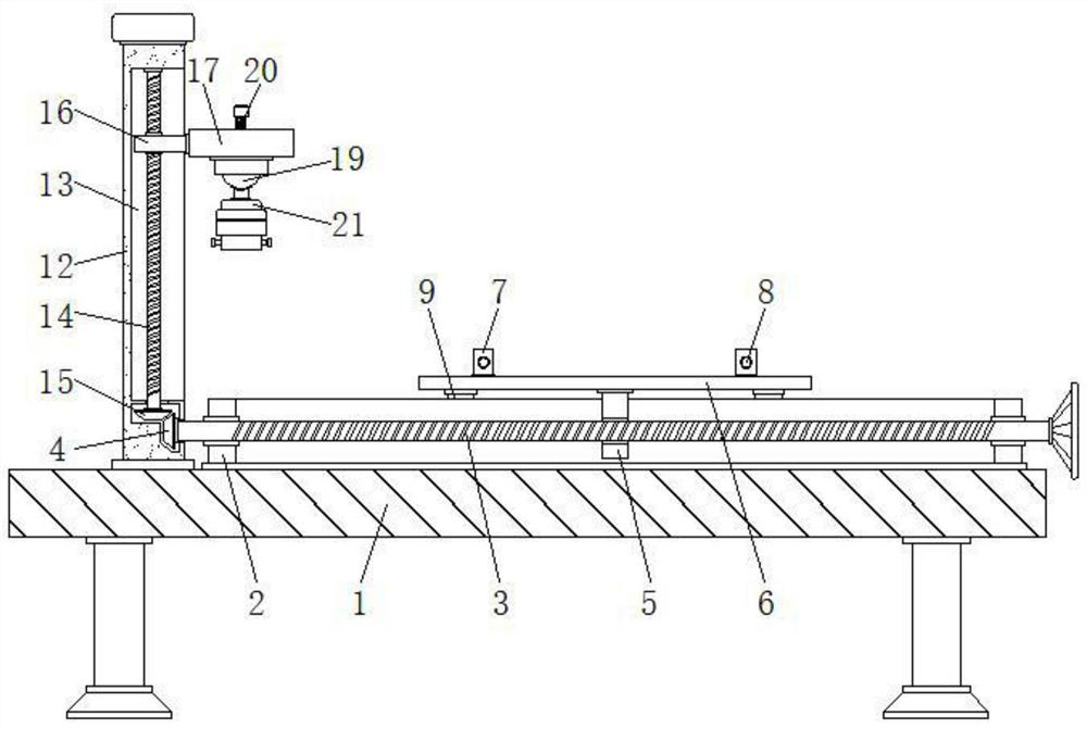
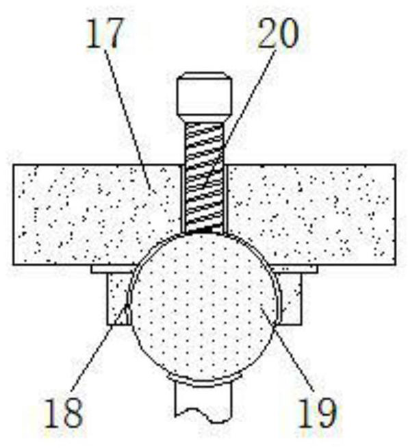
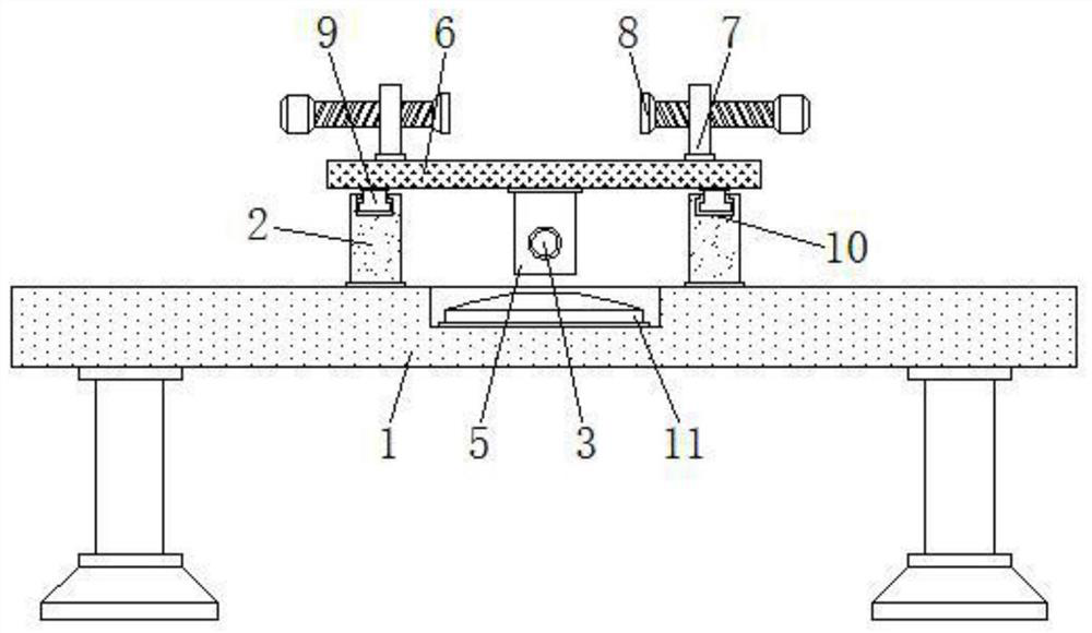
[0026] see Figure 1-6 , the present invention provides a technical solution: a horizontal installation device for a cantilever power system for an unmanned aerial vehicle, comprising an installation platform 1, a first bevel gear 4, a circular vial 11 and a second bevel gear 15, the installation platform 1 An adjustment frame 2 is arranged on the top of the adjustment frame 2, and an adjustment rod 3 is installed on the adjustment frame 2. The first bevel gea...


PUM


Abstract

The invention discloses a horizontal installation device for a cantilever power system for an unmanned aerial vehicle, comprising an installation platform, a first bevel gear, a circular vial and a second bevel gear, an adjustment frame is arranged above the installation platform, and An adjustment rod is installed on the adjustment frame, the first bevel gear is installed on the left end of the adjustment rod, and a push plate is arranged on the outside of the adjustment rod, and a horizontal plate is connected to the top of the push plate, and the horizontal plate is located on the adjustment frame. Above, the inner side of the leveling collar is provided with a solution, and the lower end of the installation cover is equipped with a limit bolt, and the limit bolt is located below the leveling collar. The drone uses a cantilever power system horizontal installation device. The installation platform can be aligned horizontally through a circular level bubble to maintain the level of the installation platform itself, and then it is convenient to cantilever the drone on the horizontal plate through the clamping bolts. It is firmly clamped, which is convenient to adapt to different sizes and models of the drone cantilever, and at the same time facilitates the horizontal placement of the drone cantilever.

Description

technical field [0001] The invention relates to the technical field of unmanned aerial vehicles, in particular to a horizontal installation device for a cantilever power system for an unmanned aerial vehicle. Background technique [0002] UAV is a small flying machine, which is mostly used for aerial photography or auxiliary agricultural drug spraying. Most of the existing UAV parts are assembled manually by workers, especially the cantilever UAV. The flying cantilever and the end of the cantilever All power motor systems need to be manually assembled, but the existing drones usually have the following problems during the installation of the cantilever motor power system: [0003] 1. The efficiency of manual installation is low, and the assembly accuracy is not high at the same time, which cannot guarantee the horizontal state of the power motor installation, which will easily lead to instability of the UAV during flight, resulting in the inability of the UAV to operate duri...

Claims


Application Information

Patent Timeline
Patent Type & Authority Patents(China)
IPC IPC(8): B64F5/10
CPCB64F5/10
Inventor 张亚锋马海英张旭辉郭卜源段领苟灵生
Owner 武汉鑫泽科技有限公司
Why Eureka
Try Eureka