Multi-push-head carbon block ungrouping device and ungrouping method in electrolytic aluminum production
A technology of electrolytic aluminum and blocks, which is applied in the field of electrolytic aluminum production to achieve the effect of reducing failure rate and cost
- Summary
- Abstract
- Description
- Claims
- Application Information
AI Technical Summary
Problems solved by technology
Method used
Image

Examples
Embodiment Construction
[0024] The present invention is described in detail below in conjunction with accompanying drawing:
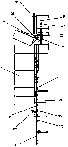
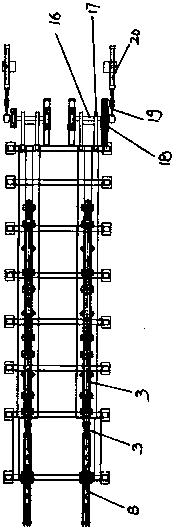
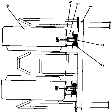
[0025] A multi-push carbon body block ungrouping device in the production of electrolytic aluminum, including a carbon body block ungrouping workbench 1, on which a carbon body block ungrouping workbench 1 is fixedly equipped with an ungrouping trolley running two parallel workers I-shaped steel track 2, an ungrouping trolley 3 is movable between the two inner flange plates of the two parallel I-steel tracks 2 on the ungrouping trolley. The top surface of the steel track is fixedly welded with an I-shaped steel slide rail 4, and a carbon body block group 6 is arranged between the top surfaces of the two I-shaped steel slide rails 4. The side is provided with a transmission line 14 after the ungrouping of the carbon body block. On the ungrouping trolley 3, along the left and right horizontal directions, the push head swing rod support 10 is arranged at equal intervals, and the ...
PUM
 Abstract
Description
Claims
Application Information
 - R&D
- Intellectual Property
- Life Sciences
- Materials
- Tech Scout
- Unparalleled Data Quality
- Higher Quality Content
- 60% Fewer Hallucinations
Browse by: Latest US Patents, China's latest patents, Technical Efficacy Thesaurus, Application Domain, Technology Topic, Popular Technical Reports.
© 2025 PatSnap. All rights reserved.Legal|Privacy policy|Modern Slavery Act Transparency Statement|Sitemap|About US| Contact US: help@patsnap.com