

Magnetic coupling transmission sealing device with efficient heat exchange system
A heat exchange system and magnetic coupling technology, which is applied in heat exchanger sealing devices, engine seals, heat exchanger shells, etc., can solve the problem of magnetic coupling drives without heat exchange systems, large converted energy, and large motor power. problem, to achieve better heat transfer effect, protection of magnetic materials, and high torque effect
- Summary
- Abstract
- Description
- Claims
- Application Information
AI Technical Summary
Problems solved by technology
Method used
Image

Examples
Embodiment Construction
[0035] The present invention will be further described below in conjunction with the examples.
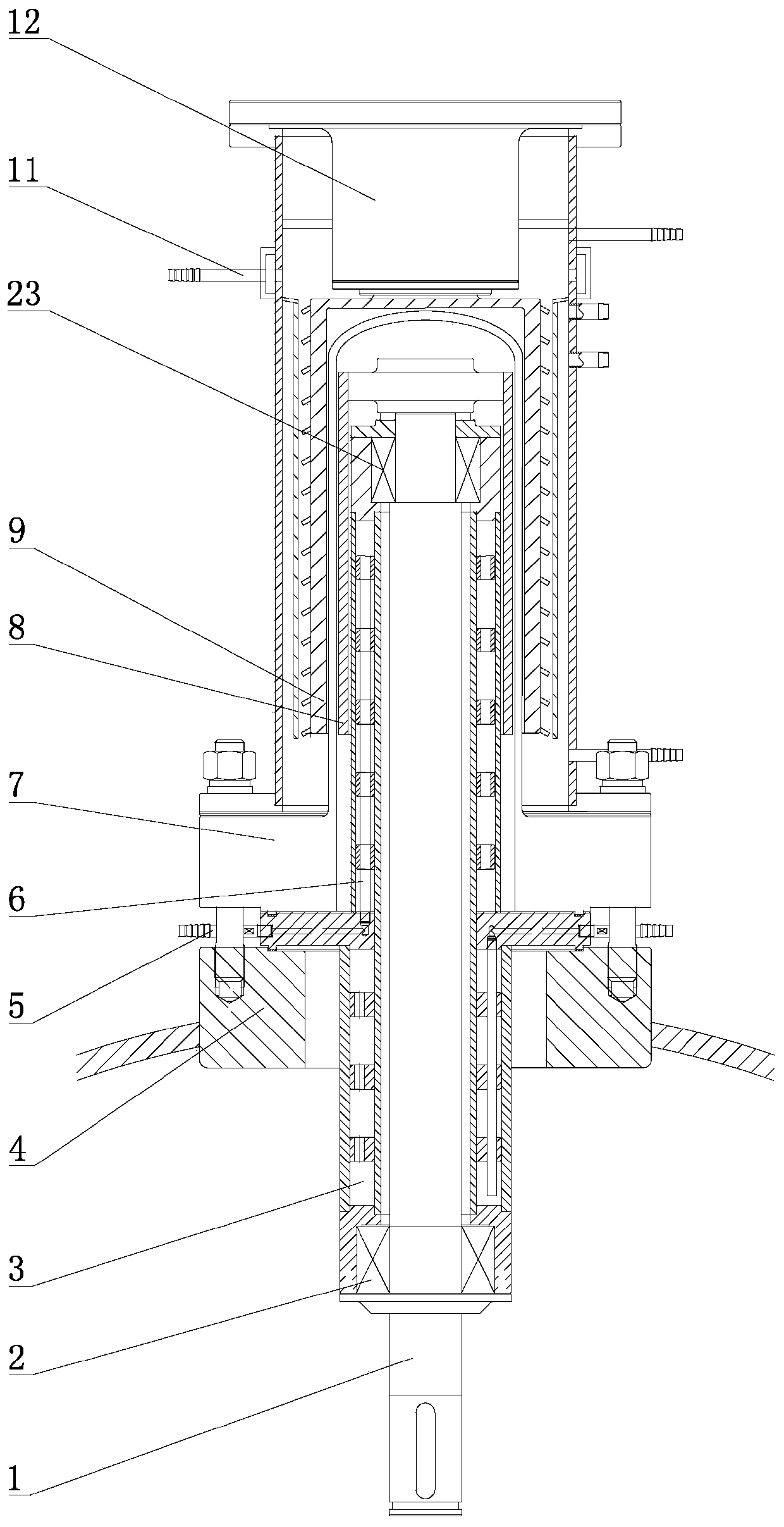
[0036] like figure 1 As shown, a magnetic coupling transmission sealing device with a high-efficiency heat exchange system includes an outer magnetic steel assembly 9, a sealing cover assembly 7, an inner magnetic steel assembly 8, an upper transmission shaft 1 and a bearing set. The above-mentioned components and interconnection are the same as those in the prior art, and are well known to those skilled in the art, and will not be repeated here.
[0037] The upper transmission shaft 1 and the bearing set are provided with an internal heat exchange assembly, and the external magnetic steel assembly 9 is provided with an external heat exchange assembly. The upper ends of the thermal assembly and the external magnetic steel assembly 9 are connected with an upper liquid sealing assembly 39 .
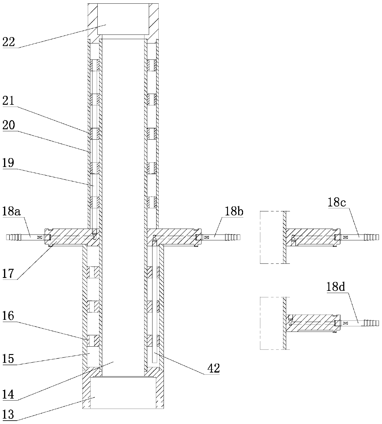
[0038] like figure 2As shown, the internal heat exchange assembly includes an upper heat...
PUM
 Abstract
Description
Claims
Application Information