
Air purification equipment for factories

An air purification equipment and factory technology, applied in the field of air purification, can solve the problems of inconvenient replacement of filter elements, affect the use effect, affect production, etc., and achieve the effect of improving the use effect and facilitating the collection.

Active Publication Date: 2020-07-03
南通安强工程科技有限公司
View PDF5 Cites 4 Cited by
  • Summary
  • Abstract
  • Description
  • Claims
  • Application Information

AI Technical Summary

Problems solved by technology

[0003] However, in the actual use of traditional factory air purification equipment, since the filter mechanism of the first layer will always filter out most of the impurities with larger particles, the filter mechanism of the first layer cannot be used for a long time. Avoid a large amount of dust and impurities, which will affect the use effect; at the same time, the gas discharged from the processing environment of the chemical plant contains various organic solvents, inorganic and organic sulfides, hydrocarbons, chlorine, oil, mercury and other environmental hazards. Harmful ingredients need to be adsorbed by activated carbon before being discharged. In this process, when there are many harmful ingredients, the adsorption function of activated carbon is often not enough to completely absorb the harmful ingredients; after a long time of use, traditional equipment is not convenient. Replace the filter element; in addition, in the production of chemical plants, it is very sensitive to large changes in the ambient air humidity, and under the influence of drying, the air humidity will plummet, and a large amount of static electricity seriously affects the smooth progress of production

Method used


Image

  • Air purification equipment for factories
  • Air purification equipment for factories
  • Air purification equipment for factories

Examples


Embodiment Construction

[0026] In order to make the technical means, creative features, goals and effects achieved by the present invention easy to understand, the present invention will be further described below in conjunction with specific embodiments.

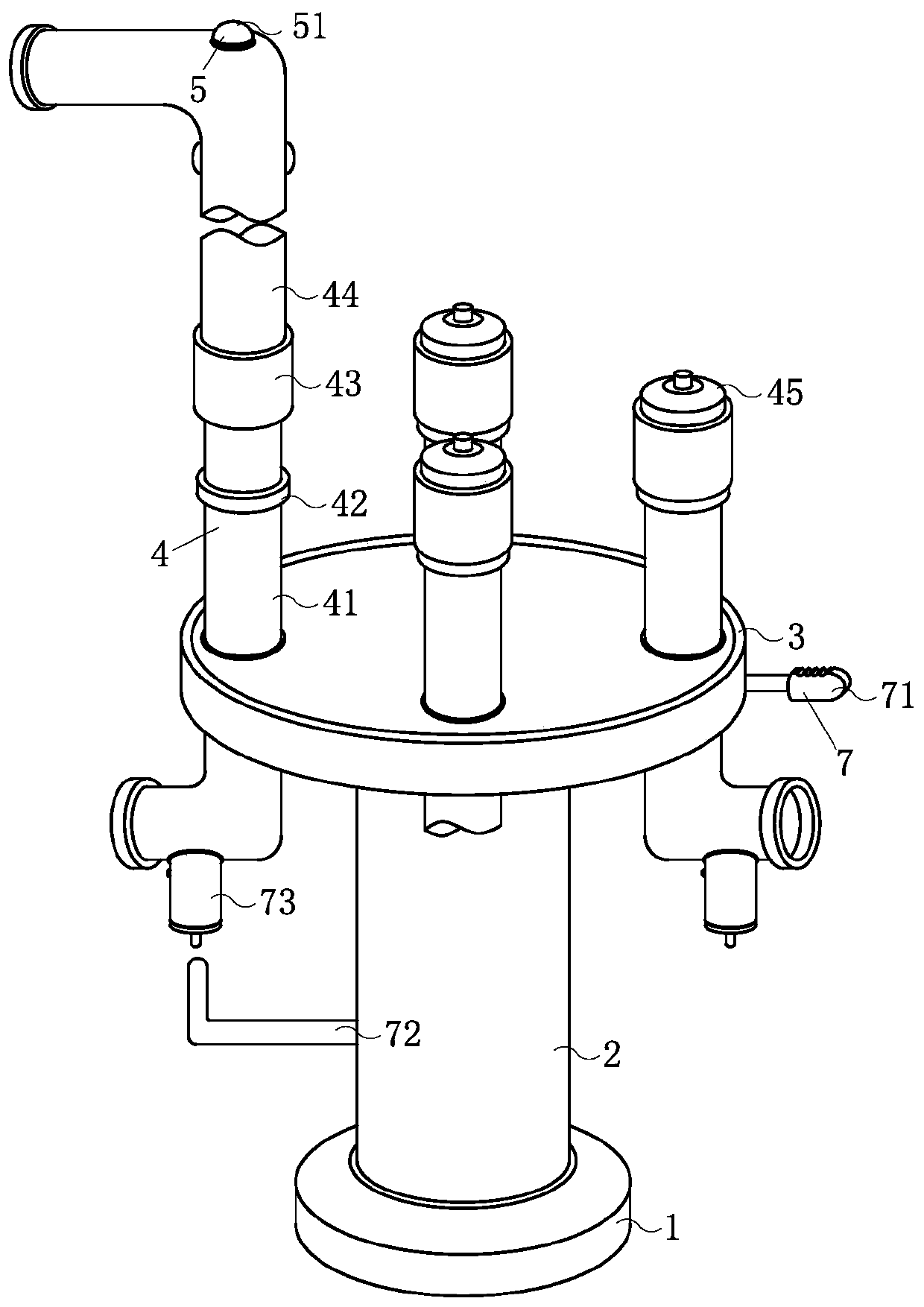
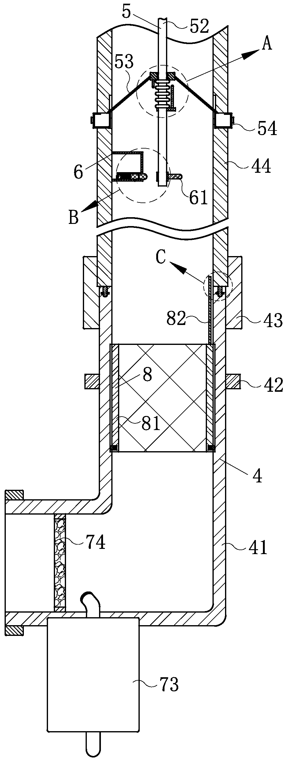
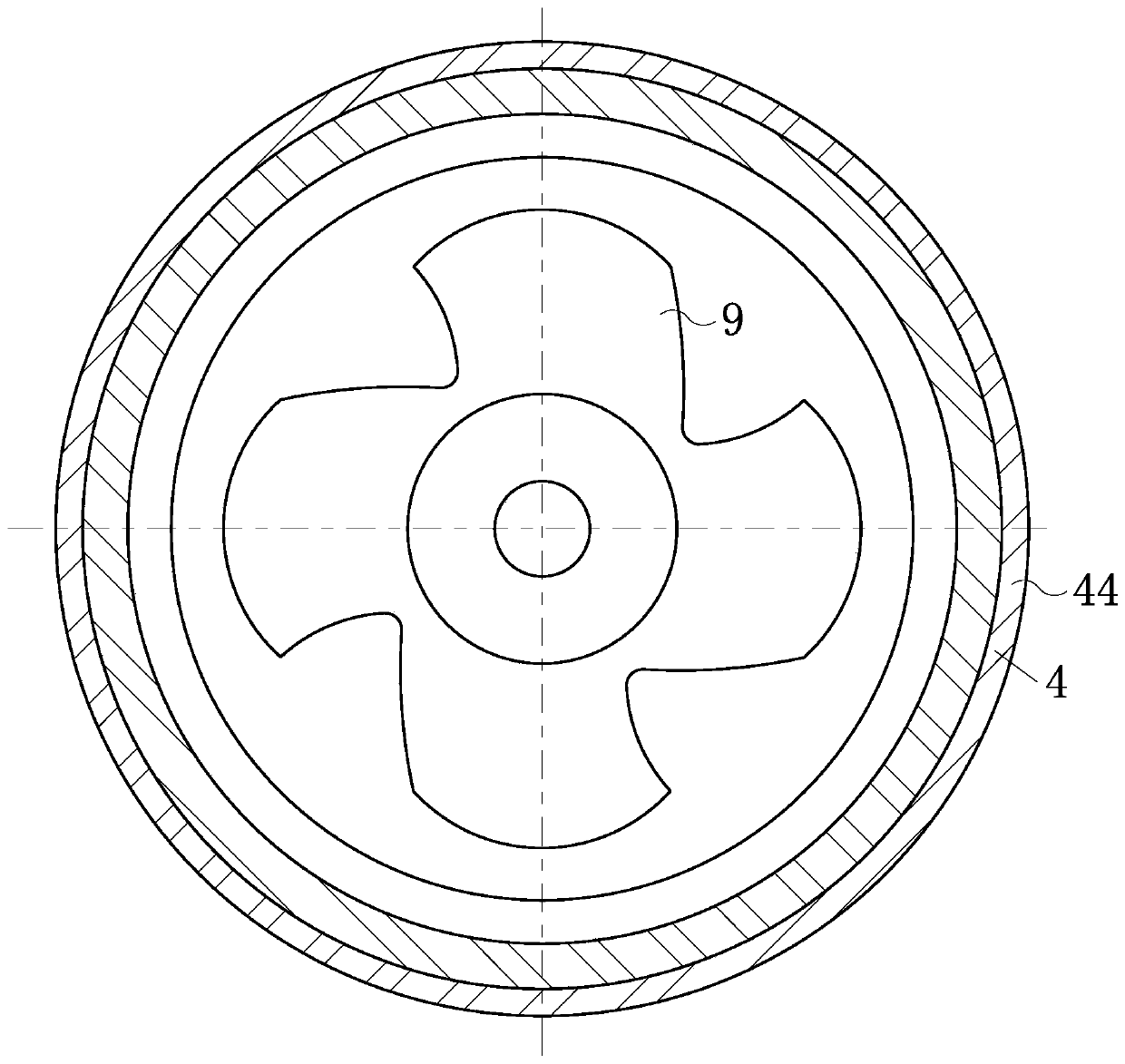
[0027] Such as Figure 1-Figure 8 As shown, an air purification device for factories according to the present invention includes a base 1, a support rod 2, an installation platform 3, a pipe mechanism 4, a purification mechanism 5, a feeding mechanism 6, a humidification mechanism 7, and a filter element mechanism 8 and the fan main body 9, the top of the base 1 for fixing the whole device is fixed with the strut 2 for supporting the whole device, and the top of the strut 2 is rotatably connected to the The installation platform 3 that other mechanisms play a role in placement, the installation platform 3 is provided with the described pipe mechanism 4 for ventilation, and the top of the inner cavity of the pipe passage mechanism 4 is provided wit...


PUM


Abstract

The invention relates to the field of air purification, in particular to air purification equipment for factories. The air purification equipment comprises a base, a supporting rod, an installation table, a through pipe mechanism, a purification mechanism, a feeding mechanism, a humidifying mechanism, a filter element mechanism and a fan main body. According to the air purification equipment, thepurification mechanism rotates inside the through pipe mechanism, and a large amount of impurities adsorbed for the first time can be conveniently shaken off, so that the purification mechanism can beprevented from being blocked; under the rotation of the purification mechanism, the feeding mechanism can automatically and continuously add decomposition agents of harmful substances to a filter element inside the through pipe mechanism in the use process, so that the equipment has a better purification effect on harmful components in gas; the humidifying mechanism is rotated, the humidity of the filtered gas is conveniently adjusted under the matching of the through pipe mechanism, and the influence of the dry air on production is avoided; and the filter element mechanism is arranged in themiddle of an inner cavity of the through pipe mechanism, and through the matched operation with the humidifying mechanism, the rapid replacement of the filter element in the equipment is convenientlyrealized.

Description

technical field [0001] The invention relates to the field of air purification, in particular to an air purification device used in factories. Background technique [0002] Air purification equipment (also known as "air cleaning equipment", air fresheners) refers to products that can filter out or kill air pollutants and effectively improve air cleanliness. Household and commercial air purification equipment that remove indoor air pollution are the main products. host. Air purification equipment can filter airborne particulates, bacteria, viruses, fungal spores, pollen, asbestos, radon decay products and other pollutants. According to the application field, it can be divided into: household air purification equipment, vehicle air purification equipment (also known as vehicle air purification equipment), medical air purification equipment, industrial air purification equipment and engineering air purification equipment. Among them, due to the particularity of production in s...

Claims


Application Information

Patent Timeline
IPC IPC(8): F24F3/14F24F3/16F24F13/02F24F13/28
CPCF24F3/14F24F13/02F24F13/28F24F8/10F24F8/108F24F8/15
Inventor 李贤明李乐水李永红
Owner 南通安强工程科技有限公司
Learn More