Unmanned vehicle obstacle avoidance method and system based on obstacle configuration reconstruction

An obstacle, unmanned vehicle technology, applied in the field of obstacle avoidance methods and systems for unmanned vehicles based on obstacle configuration reconstruction, can solve the problem of inaccurate obstacle size estimation, and achieve real-time obstacle size and real-time estimation. Effect

Active Publication Date: 2020-07-03
郴州职业技术学院
View PDF6 Cites 7 Cited by
  • Summary
  • Abstract
  • Description
  • Claims
  • Application Information

AI Technical Summary

Problems solved by technology

[0004] In order to solve the problem of inaccurate estimation of the size of obstacles in the existing unmanned vehicle obstacle avoidance methods in the background technology, the present invention provides an unmanned vehicle obstacle avoidance method and system based on obstacle configuration reconstruction, specific technical solutions as follows

Method used


Image

  • Unmanned vehicle obstacle avoidance method and system based on obstacle configuration reconstruction
  • Unmanned vehicle obstacle avoidance method and system based on obstacle configuration reconstruction
  • Unmanned vehicle obstacle avoidance method and system based on obstacle configuration reconstruction

Examples


Embodiment 1

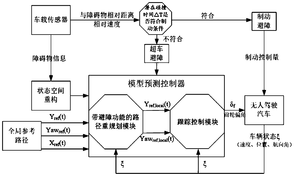
[0068] see Figure 1-Figure 6 , an unmanned vehicle obstacle avoidance method based on obstacle configuration reconstruction, including the following steps:

[0069] Step 1: According to the obstacle state information collected by the on-board sensor (relative distance and relative speed to the closest point of the obstacle), establish the △T potential collision time, set the braking conditions, and judge whether to perform braking obstacle avoidance or execute Overtaking and obstacle avoidance;

[0070] Specifically, step 1 specifically includes:

[0071] Step 1.1, according to the obstacle state information (relative distance and relative speed from the closest point to the obstacle) collected by the vehicle sensor (composed of long-distance millimeter-wave radar, short-distance millimeter-wave radar and visual camera sensor), calculate the potential collision time △ T controls the amount of braking, ie:

[0072]

[0073] Among them, △S is the relative distance to the ...

Embodiment 2

[0124] An unmanned vehicle obstacle avoidance system, comprising:

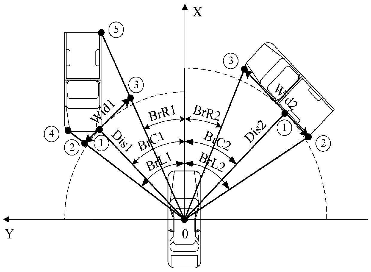
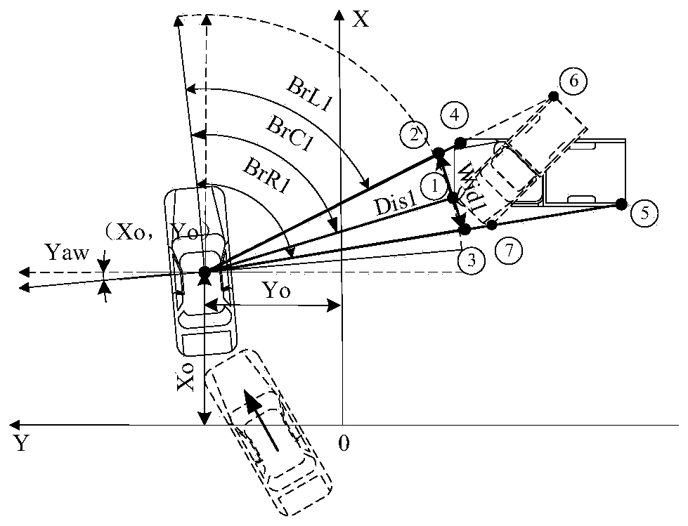
[0125] The configuration reconstruction module is used to reconstruct the obstacle data in the global coordinate system to obtain the reconstructed obstacle configuration information points;

[0126] The penalty function building module is used to establish the following penalty function when predicting the i-th time domain according to the reconstructed obstacle configuration information point: Among them, S obs is the weight coefficient; v is the relative speed between the unmanned vehicle and the obstacle; x m ,y m is the coordinate of the mth information point of the reconstructed obstacle configuration in the global coordinate system; x 0 ,y 0 is the coordinate of the unmanned vehicle in the global coordinate system; ζ is a positive number;

[0127] The objective function building module is used to set up the following objective function according to the penalty function:

[0128] Among them, J ...


PUM


Abstract

The invention discloses an unmanned vehicle obstacle avoidance method and system based on obstacle configuration reconstruction. The method comprises steps of reconstructing obstacle data under a global coordinate system, building a corresponding target function, and solving the optimal solution of the target function to obtain an unmanned vehicle obstacle avoidance optimal path. The method is advantaged in that compared with the prior art, an expansion configuration (double splayed, circular, elliptical or rectangular configuration) with a safety area is reconstructed, the reconstructed expansion configuration is reconstructed according to the detected obstacle data, therefore, even if the reconstructed expansion configuration deviates when the obstacle data is detected for the first time, the obstacle data can be continuously detected in real time, and obstacle configuration is continuously adjusted according to the obstacle data, so the size of the obstacle is estimated more accurately in real time, and finally, obstacle avoidance path planning of the unmanned vehicle is realized.

Description

technical field [0001] The invention relates to the technical field of automatic driving, in particular to an obstacle avoidance method and system for an unmanned vehicle based on obstacle configuration reconstruction. Background technique [0002] As one of the key technologies in the research of unmanned vehicles, local path planning replans the local optimal path to avoid obstacles based on the obstacle information collected by the vehicle sensor and the global expected path information, focusing on relying on the vehicle sensor (millimeter wave Radar, lidar, visual camera, etc.) to collect information, which has strong real-time performance. At present, local path planning methods can be classified into two categories: traditional local path planning methods and intelligent local path planning methods. Traditional local path planning methods mainly include artificial potential field method, grid method, and vector field histogram method. It is acceptable to deal with ob...

Claims


Application Information

Patent Timeline
Patent Type & Authority Applications(China)
IPC IPC(8): G05D1/02
CPCG05D1/0217G05D2201/0212Y02T10/40
Inventor 雷芳华袁小芳
Owner 郴州职业技术学院
Why Eureka
Try Eureka