Method and device for controlling lane flow

A lane and flow technology, applied in the field of intelligent transportation, can solve problems such as waste of lane resources, unbalanced traffic flow on lanes, and unbalanced traffic flow on lanes

Inactive Publication Date: 2020-07-03
BEIJING DIDI INFINITY TECH & DEV
View PDF16 Cites 4 Cited by
  • Summary
  • Abstract
  • Description
  • Claims
  • Application Information

AI Technical Summary

Problems solved by technology

At present, in scenarios such as commuting morning and evening rush hours, it is often seen that the traffic flow of the same road section in different directions is unbalanced. During the morning peak hours, the number of vehicles on the outbound lanes is much smaller than the number of vehicles on the inbound direction, and the lane resources in the outbound direction are w

Method used


Image

  • Method and device for controlling lane flow
  • Method and device for controlling lane flow
  • Method and device for controlling lane flow

Examples


Embodiment 1

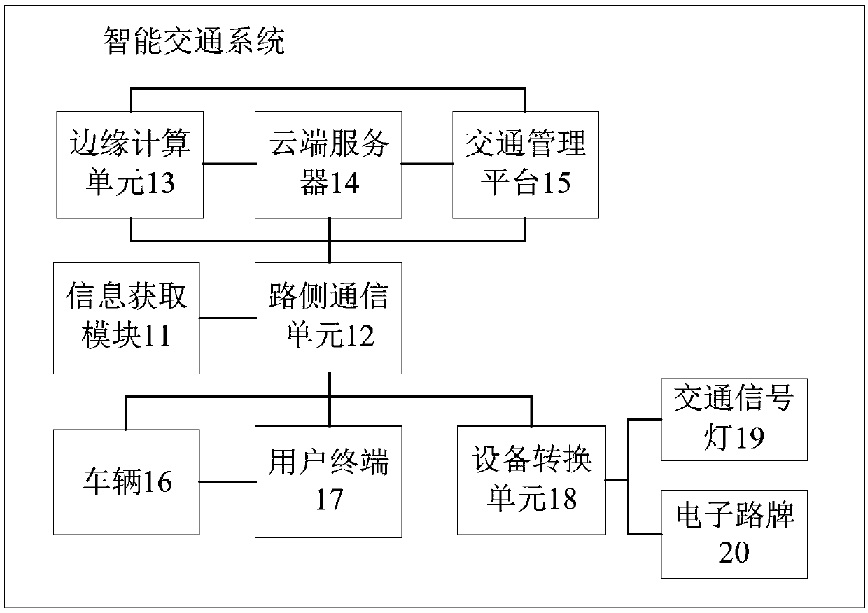
[0076] see figure 1 As shown, it is a schematic diagram of the overall networking architecture of an intelligent transportation system provided by the embodiment of the present application, including:

[0077] Information acquisition module 11; roadside communication unit 12; edge computing unit 13; cloud server 14; traffic management platform 15; vehicle 16; user terminal 17; equipment conversion unit 18; traffic lights 19;

[0078] The information acquisition module 11 includes information collection equipment deployed at road intersections and intermediate road sections, such as cameras, laser radars, etc.; laser radar and cameras can collect road condition information at road intersections or intermediate road sections, and upload them through the roadside communication unit 12. To the cloud server 14 and / or the edge computing unit 13, the road conditions are analyzed by the cloud server 14 and / or the edge computing unit 13;

[0079] The roadside communication unit 12 is ...

Embodiment 2

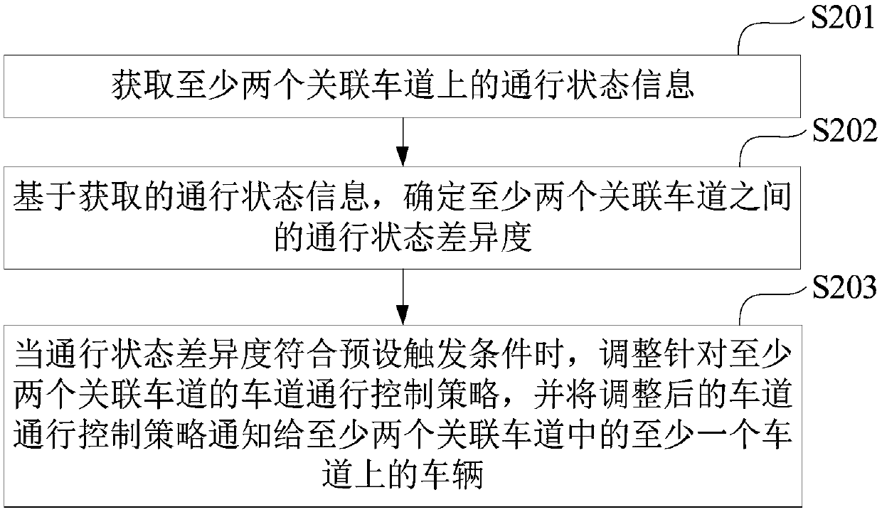
[0090] see figure 2 As shown, it is a schematic flowchart of a method for controlling lane flow provided by an embodiment of the present application, including the following steps:

[0091] S201: Obtain traffic status information on at least two associated lanes.

[0092] S202: Based on the acquired traffic state information, determine a traffic state difference between at least two associated lanes.

[0093] S203: When the traffic state difference meets the preset trigger condition, adjust the lane traffic control strategy for at least two associated lanes, and notify the adjusted lane traffic control strategy to at least one of the at least two associated lanes. vehicle.

[0094] In a possible implementation manner, the passing status information includes at least one of the following information: vehicle passing speed, and the number of vehicles queuing at road intersections. It can be understood that the number of vehicles on the lane can be known through the above at le...

Embodiment 3

[0176] Such as Figure 8 As shown, it is a schematic structural diagram of a device 80 for controlling traffic flow in a lane provided in Embodiment 3 of the present application, including:

[0177] An acquisition module 81, configured to acquire traffic state information on at least two associated lanes;

[0178] A determination module 82, configured to determine the degree of difference in the traffic state between the at least two associated lanes based on the acquired traffic state information;

[0179] A processing module 83, configured to adjust the lane traffic control strategy for the at least two associated lanes when the traffic state difference meets the preset trigger condition, and notify the at least two associated lanes of the adjusted lane traffic control strategy. vehicles on at least one of the associated lanes.

[0180] In a possible design, the passing state information includes at least one of the following information: vehicle passing speed, and the num...


PUM


Abstract

The invention relates to the technical field of intelligent transportation, and especially relates to a method and a device for controlling lane flow. The method comprises the following steps: acquiring traffic state information on at least two associated lanes; determining a traffic state difference degree between the at least two associated lanes based on the acquired traffic state information;and when the traffic state difference degree meets a preset triggering condition, adjusting a lane traffic control strategy for the at least two associated lanes, and notifying vehicles on at least one lane in the at least two associated lanes of the adjusted lane traffic control strategy. By the adoption of the scheme, the traffic control strategy can be adjusted in time according to the trafficstate on the lane, lane resources can be effectively utilized, and lane traffic pressure in the peak period is relieved.

Description

technical field [0001] The present application relates to the technical field of intelligent transportation, in particular to a method and device for controlling lane flow. Background technique [0002] With the complexity of the urban traffic road network and the increase in the number of cars, traffic congestion is becoming more and more serious. At present, in scenarios such as commuting morning and evening rush hours, it is often seen that the traffic flow of the same road section in different directions is unbalanced. During the morning peak hours, the number of vehicles on the outbound lanes is much smaller than the number of vehicles on the inbound direction, and the lane resources in the outbound direction are wasted; while in the evening peak hours, the number of vehicles in the outbound direction is much greater than the number of vehicles in the cityward direction. Direction lane resources are wasted. It can be seen that the current configuration of lanes may ha...

Claims


Application Information

Patent Timeline
IPC IPC(8): G08G1/01G08G1/08G08G1/09
CPCG08G1/0145G08G1/08G08G1/09
Inventor 苗伟
Owner BEIJING DIDI INFINITY TECH & DEV
Why Eureka
Try Eureka