Self-powered field waterfall danger warning equipment

A self-powered, field technology, applied in the field of field safety warnings, can solve problems such as external environmental interference damage, solar power supply equipment can not work for a long time, danger, etc., to increase stability, increase stability and reliability of warnings, increase reliability effect

Active Publication Date: 2020-07-03
国网江苏省电力有限公司启东市供电分公司 +1
View PDF5 Cites 1 Cited by
  • Summary
  • Abstract
  • Description
  • Claims
  • Application Information

AI Technical Summary

Problems solved by technology

[0004] The purpose of the present invention is to solve the disadvantages in the prior art that the isolation belt warning is relatively simple, easily damaged by external environment interference, and the solar power supply equipment cannot work for a long time due to environmental reasons, and proposes a self-powered outdoor waterfall danger warning equipment

Method used


Image

  • Self-powered field waterfall danger warning equipment
  • Self-powered field waterfall danger warning equipment
  • Self-powered field waterfall danger warning equipment

Examples


Embodiment 1

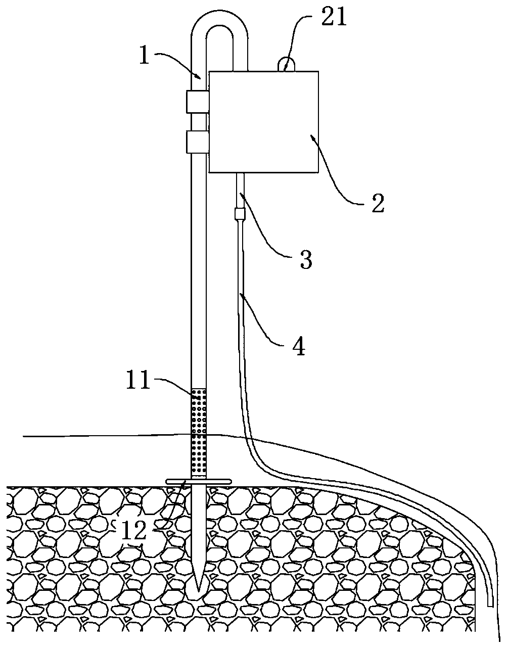
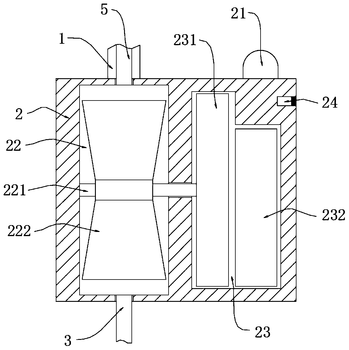
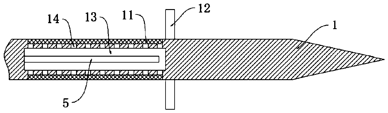
[0028] refer to Figure 1-3 , a self-powered outdoor waterfall danger warning device, including a fixed rod 1 inserted on the edge of the river, a box body 2 is installed on the fixed rod 1, the upper end of the fixed rod 1 is bent and installed on the upper end of the box body 2, and the inside of the fixed rod 1 A suction pipe 5 is embedded and installed, and a conversion chamber 22 and a power chamber 23 are opened in the box body 2 respectively. The impeller 222 is installed, the rotating shaft 221 extends into the power cavity 23 and a disc generator 231 is installed, the battery 232 is installed in the power cavity 23, and the lower bottom wall of the conversion cavity 22 is inserted and communicated with an overflow pipe 3, the overflow pipe The lower end of 3 is sealed with a hose 4, the lower end of the fixed rod 1 is installed with a fixed plate 12, the upper end of the fixed rod 1 is located at the upper end of the fixed plate 12, and a water filter chamber 13 is op...

Embodiment 2

[0034] refer to Figure 4-6 , a self-powered wild waterfall danger warning device, which is basically consistent with Embodiment 1, the difference is that:

[0035] The middle section of the fixed rod 1 is equipped with a balance pipe 6, and the suction pipe 5 runs through the balance pipe 6. A pipe sleeve 61 is installed on the suction pipe 5. The upper and lower ends of the pipe sleeve 61 are symmetrically equipped with swirl vanes 62. The middle section of the pipe sleeve 61 is installed on the outer wall. There are a plurality of connecting rods 63, and a ferrule 64 is sealed and rotatably embedded on the side wall of the balance tube 6, and a plurality of connecting rods 63 are fixedly installed on the inner wall of the ferrule 64, and a balance plate 65 is installed on the outer wall of the ferrule 64 , the balance plate 65 is provided with a swirl groove 651;

[0036] When the water flow enters the balance pipe 6, the pipe sleeve 61 can be rotated by the swirl vane 62,...


PUM


Abstract

The invention discloses self-powered field waterfall danger warning equipment comprising a fixed rod inserted into the edge of a riverway and characterized in that a box body is mounted on the fixed rod; the upper end of the fixed rod is mounted at the upper end of the box body in a bent mode; a suction pipe is embedded in the fixed rod; a conversion cavity and an electric power cavity are formedin the box body, the upper end of the suction pipe extends to the upper end of the interior of the conversion cavity, a rotating shaft is rotatably inserted into the conversion cavity in a sealed mode, an impeller is mounted on the rotating shaft, the rotating shaft extends into the electric power cavity and is provided with a disc type electric generator, and a storage battery is mounted in the electric power cavity. The siphon phenomenon is formed through the terrain height of the suction pipe and a hose, siphon water flow drives the impeller to generate electricity for warning of a warninglamp, external power supply is not needed, the self-powered field waterfall danger warning equipment is more suitable for mountain forests compared with solar power supply, the equipment is fixed morestably through rotation of a balance disc, and the reliability of warning of the equipment is further improved.

Description

technical field [0001] The invention relates to the field of field safety warning, in particular to a self-powered field waterfall danger warning device. Background technique [0002] In our country, many areas are mountainous forest landforms, and there are many streams and waterfalls in the mountain forests. For some field explorers, they often pass through these mountain forests, and the scattered waterfalls will bring the explorers a lot of trouble when the sky is dark. come dangerous. [0003] Existing dangerous areas such as waterfalls are usually blocked by isolation belts, but the isolation belts are easily damaged or blown away by the wind, resulting in inaccurate positioning. However, due to the mountains and forests, the temperature is low, and the amount of sunlight is less, some solar energy The power supply warning device cannot work for a long time. Contents of the invention [0004] The purpose of the present invention is to solve the disadvantages in the...

Claims


Application Information

Patent Timeline
Patent Type & Authority Applications(China)
IPC IPC(8): G09F13/22F03B13/08F03B11/08
CPCG09F13/22F03B13/086F03B11/08Y02E10/20
Inventor 郑晓群
Owner 国网江苏省电力有限公司启东市供电分公司
Why Eureka
Try Eureka