Piezoelectric module and electronic device

A module and piezoelectric technology, applied in the direction of piezoelectric/electrostrictive/magnetostrictive devices, circuits, electrical components, etc., can solve problems such as electrode erosion, affecting the stability of substrates and piezoelectric units, and affecting stability

Inactive Publication Date: 2020-07-03
NANCHANG OUFEI BIOLOGICAL IDENTIFICATION TECH
View PDF0 Cites 1 Cited by
  • Summary
  • Abstract
  • Description
  • Claims
  • Application Information

AI Technical Summary

Problems solved by technology

However, regardless of where the conductive bonding structure is located, the conductive bonding structure is at least partially exposed
Since the viscosity of the conductive adhesive structure is greatly affected by the temperature and humidity in the environment, it affects the stability of the electrical connection between the substrate and the piezoelectric unit, and further causes the electrodes connected to the conductive adhesive structure in the piezoelectric unit to be affected by the intruding water and oxygen. affected by erosion
In addition, due to the leakage of the side electrodes in the piezoelectric unit and the extension electrodes located on the side of the piezoelectric unit away from the substrate, the side electrodes and extension electrodes of the leakage are also susceptible to oxidation due to the influence of water and oxygen in the environment
All of the above will affect the electrical properties of the leaking side electrodes and extension electrodes due to oxidation, or affect the stability of the electrical connection between the positive electrode and the negative electrode and the substrate respectively, thereby affecting the electrical function of the piezoelectric module.

Method used


Image

  • Piezoelectric module and electronic device
  • Piezoelectric module and electronic device
  • Piezoelectric module and electronic device

Examples


Embodiment Construction

[0038] In order to make the above objects, features and advantages of the present invention more comprehensible, specific implementations of the present invention will be described in detail below in conjunction with the accompanying drawings. In the following description, numerous specific details are set forth in order to provide a thorough understanding of the present invention. However, the present invention can be implemented in many other ways different from those described here, and those skilled in the art can make similar improvements without departing from the connotation of the present invention, so the present invention is not limited by the specific embodiments disclosed below.

[0039] It should be noted that when an element is referred to as being “fixed” to another element, it can be directly on the other element or there can also be an intervening element. When an element is referred to as being "connected to" another element, it can be directly connected to t...


PUM

PropertyMeasurementUnit
thicknessaaaaaaaaaa
thicknessaaaaaaaaaa
thicknessaaaaaaaaaa

Abstract

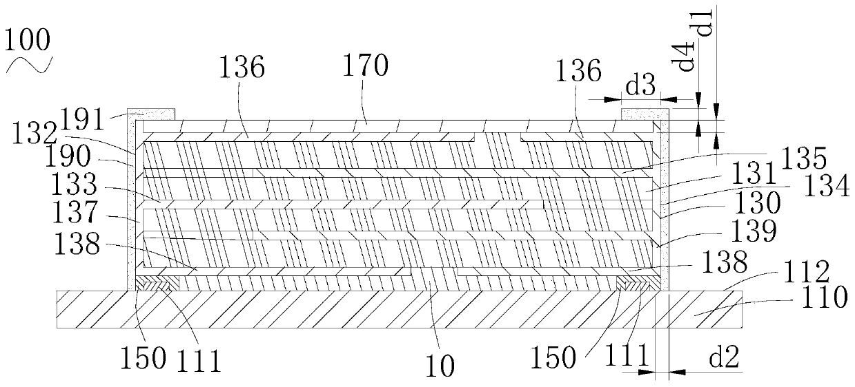
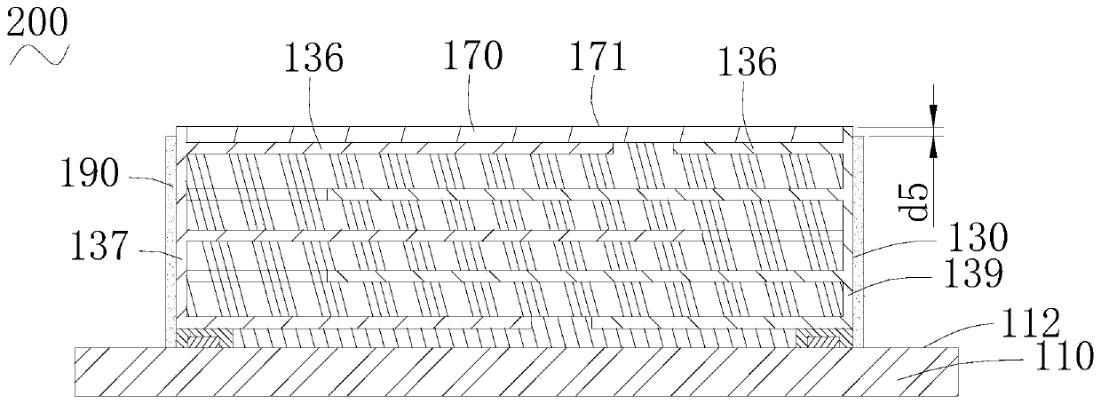
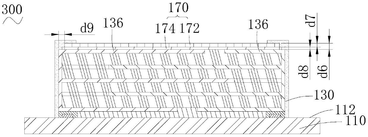
The invention relates to a piezoelectric module and an electronic device. A piezoelectric module includes a substrate having a working surface; a piezoelectric unit, arranged on the working surface ofthe substrate, the piezoelectric unit being provided with a first side and a second side which are oppositely arranged in the direction parallel to the working surface, and the first side and the second side being each provided with a side electrode; a first extension electrode, arranged on one side, far away from the substrate, of the piezoelectric unit; a conductive bonding structure, arrangedbetween the substrate and the piezoelectric unit, or arranged on the substrate and positioned on the side edge of the electrode on the corresponding side of the piezoelectric unit, so that the piezoelectric unit is electrically connected with the substrate; a first insulation protection layer, arranged on the surface, far away from the substrate, of the piezoelectric unit and covering the first extension electrode; and a second insulating protection layer covering the side electrodes on the surfaces of the first side and the second side of the piezoelectric unit and extending to the working surface of the substrate from the first side and the second side, so that the conductive bonding structure is isolated from the outside.

Description

technical field [0001] The invention relates to a piezoelectric module, in particular to a piezoelectric module and an electronic device. Background technique [0002] Traditionally, a piezoelectric module includes a substrate and a piezoelectric unit disposed on the substrate. The piezoelectric unit is electrically connected to the substrate through a conductive adhesive structure. The conductive adhesive structure is either located between the piezoelectric unit and the substrate, or located on the substrate and at one side of the piezoelectric unit. However, no matter where the conductive bonding structure is located, the conductive bonding structure is at least partially exposed. Since the viscosity of the conductive adhesive structure is greatly affected by the temperature and humidity in the environment, it affects the stability of the electrical connection between the substrate and the piezoelectric unit, and further causes the electrodes connected to the conductive...

Claims


Application Information

Patent Timeline
Patent Type & Authority Applications(China)
IPC IPC(8): H01L41/053
CPCH10N30/883
Inventor 刘伟
Owner NANCHANG OUFEI BIOLOGICAL IDENTIFICATION TECH
Why Eureka
Try Eureka