
Metering valve and jet pump unit for controlling a gaseous medium

A gaseous medium and dosing valve technology, which is applied in the direction of jet pumps, injection devices, electrical components, etc., can solve problems such as leakage and reduced sealing of dosing valves, and achieve the effect of improving the sealing and optimizing the design

Pending Publication Date: 2020-07-03
ROBERT BOSCH GMBH
View PDF12 Cites 0 Cited by
  • Summary
  • Abstract
  • Description
  • Claims
  • Application Information

AI Technical Summary

Problems solved by technology

However, this can lead to a reduction in the tightness of the metering valve and to leakages at the involved components

Method used


Image

  • Metering valve and jet pump unit for controlling a gaseous medium
  • Metering valve and jet pump unit for controlling a gaseous medium

Examples


Embodiment Construction

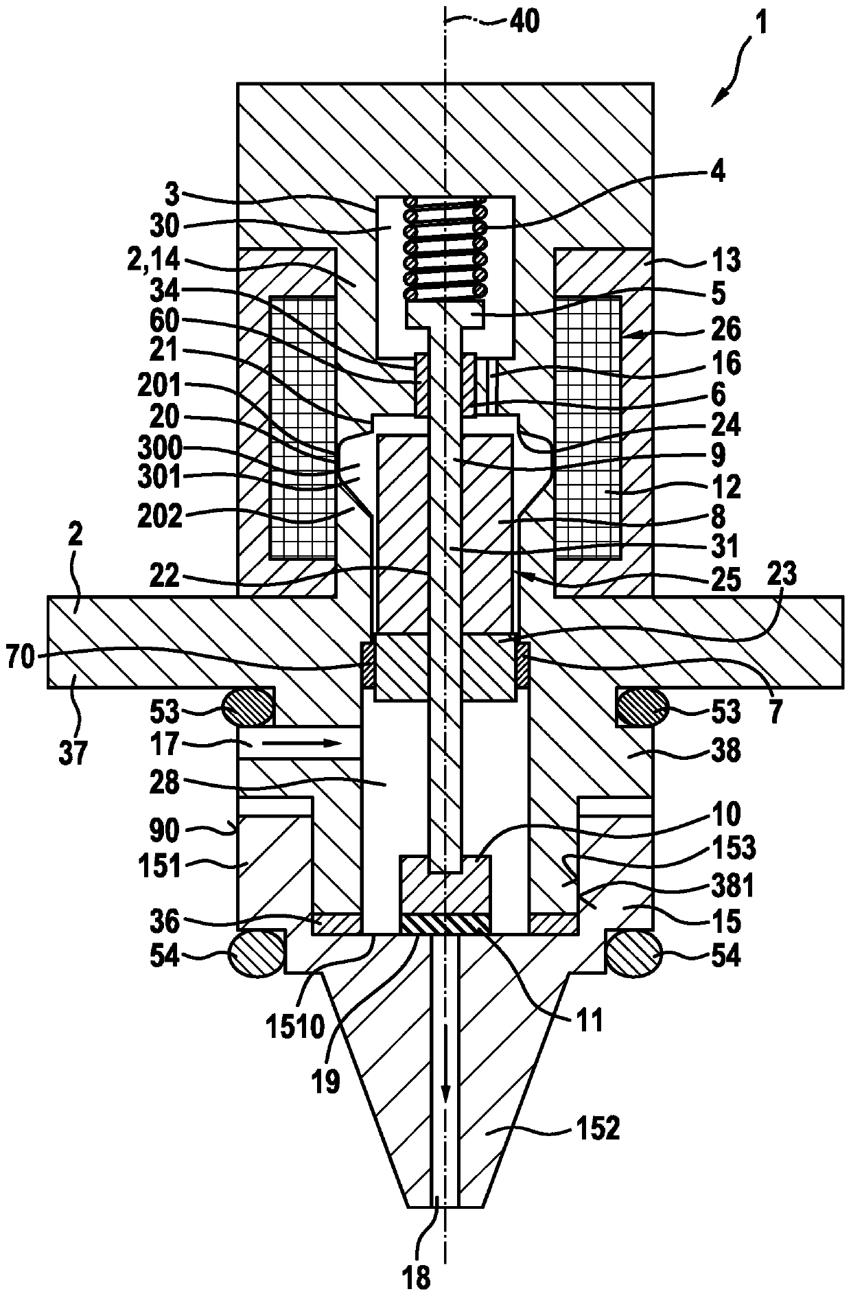
[0020] FIG. 1 shows a first embodiment of a metering valve 1 according to the invention in a longitudinal section. The metering valve 1 has a valve housing 2 which has an inner chamber 3 . Arranged in the inner chamber 3 is an electromagnet 26 comprising a solenoid coil 12 , an inner pole 14 and an outer pole 13 .

[0021] Furthermore, a reciprocating electromagnetic armature arrangement 25 is arranged in the inner chamber 3 . The magnetic armature arrangement 25 comprises the magnetic armature 8 and the connection element 9 , which is received in a recess 22 of the magnetic armature 8 and is thus fixedly connected to the magnetic armature 8 , for example by a welding seam or by pressing. The magnetic armature 8 is designed as a sunken magnetic armature and is received in the inner pole 14 . The inner pole 14 has a notch 21 with a notch edge 24 into which the magnet armature 8 sinks during its stroke movement.

[0022] Arranged in the slot 34 on the inner pole 14 is a first...


PUM


Abstract

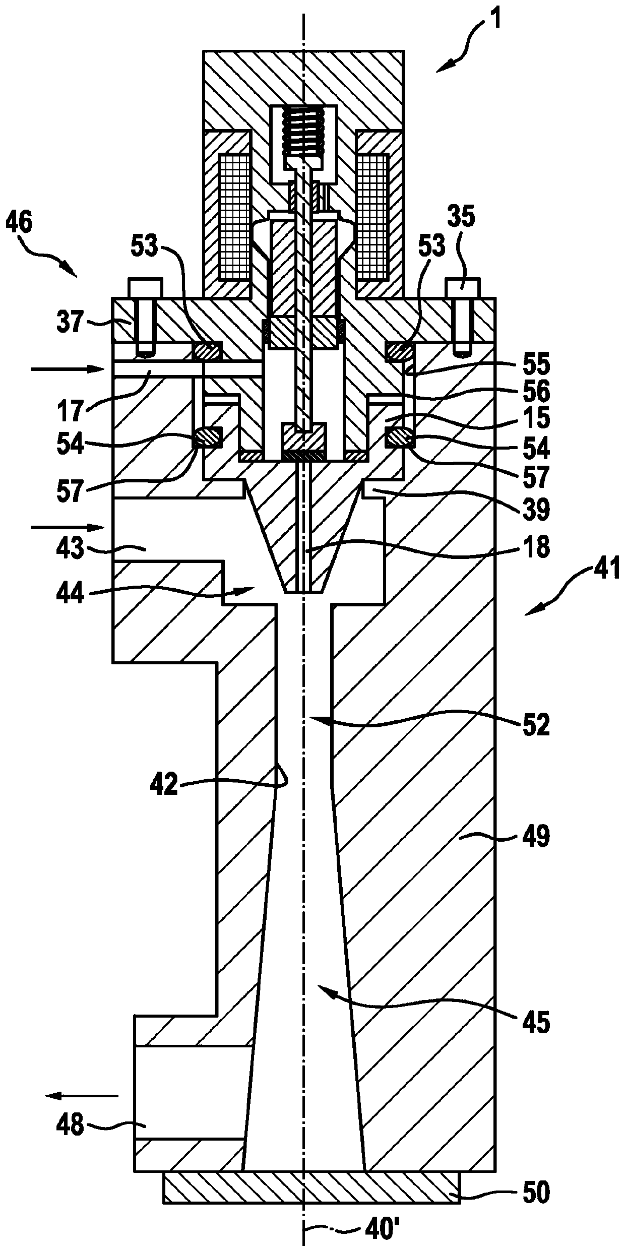
The invention relates to a metering valve (1) for controlling a gaseous medium, particularly hydrogen, comprising a valve housing (2), wherein an interior space (3) is formed in said valve housing (2). A movable closing element (10) is arranged in the interior space (3) along a longitudinal axis (40) of the metering valve (1), and said element interacts with a valve seat (19) in order to open or close off an opening cross-section of an inflow region (28) into a through-channel (18). Furthermore, the metering valve (1) comprises a nozzle (15) in which the through-channel (18) is formed and on which at least one sealing element (54) is arranged, wherein the sealing element (54) is designed to seal a gap (56) in an opening in which said nozzle (15) is received.

Description

technical field [0001] The invention relates to a metering valve and jet pump unit for controlling a gaseous medium, in particular hydrogen, which is used, for example, in a vehicle with a fuel cell drive. Background technique [0002] DE 10 2010 043 618 A1 describes a metering valve for controlling a gaseous medium, in particular hydrogen, wherein the metering valve comprises a valve housing, an injector unit, an actuator and a closing element. A throughflow opening is formed in the valve housing, which can be released or closed at the valve seat by the closing element. The ejector unit comprises: an inflow area, to which the first gaseous medium under pressure is delivered; a suction area, on which the second medium acts; and a mixing tube area, on which the first gaseous medium and the second medium The mixture of the two gaseous media flows out of this mixing tube region. The throughflow opening is arranged between the inflow region and the suction region of the inject...

Claims


Application Information

Patent Timeline
Patent Type & Authority Applications(China)
IPC IPC(8): G05D16/20F16K31/00
CPCG05D16/2013F16K31/0655B05B1/005F04F5/46H01M8/04089H01M2250/20H01M8/04201F04F5/14Y02T90/40Y02E60/50B05B5/00F16K31/00G05D16/2022F04F5/16
Inventor H-C·马格尔
Owner ROBERT BOSCH GMBH
Learn More