
Steel pipe welding positioning and clamping device

A technology for clamping devices and steel pipes, which is applied in the direction of auxiliary devices, welding equipment, auxiliary welding equipment, etc., and can solve problems such as limited scope of use and inapplicability

Inactive Publication Date: 2020-07-07
童卓超
View PDF1 Cites 5 Cited by
  • Summary
  • Abstract
  • Description
  • Claims
  • Application Information

AI Technical Summary

Problems solved by technology

[0006] The purpose of the present invention is to provide a positioning and clamping device for steel pipe welding to solve the problem that the above-mentioned device is not suitable for steel pipes of different lengths, and the clamping device is only suitable for steel pipes with fixed diameters, and the scope of use is limited.

Method used


Image

  • Steel pipe welding positioning and clamping device
  • Steel pipe welding positioning and clamping device
  • Steel pipe welding positioning and clamping device

Examples


Embodiment Construction

[0019] The following will clearly and completely describe the technical solutions in the embodiments of the present invention with reference to the accompanying drawings in the embodiments of the present invention. Obviously, the described embodiments are only some, not all, embodiments of the present invention. Based on the embodiments of the present invention, all other embodiments obtained by persons of ordinary skill in the art without creative efforts fall within the protection scope of the present invention.

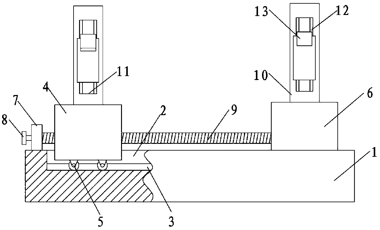
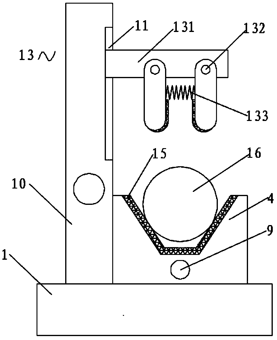
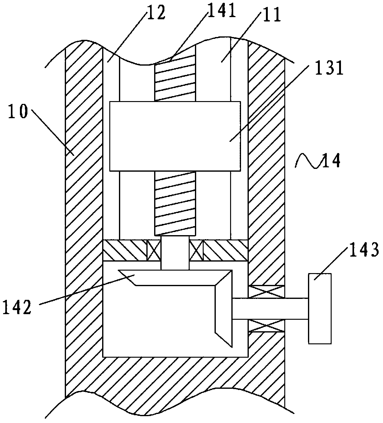
[0020] see Figure 1-3 , the present invention provides a technical solution: a positioning and clamping device for steel pipe welding, including a welding workbench 1, a movable groove 2 is provided on the top of the welding workbench 1, and a track 3 is arranged at the bottom of the inner cavity of the movable groove 2, and the track 3 3 is provided with a movable V-shaped clamping seat 4, and the bottom of the movable V-shaped clamping seat 4 is symmetrically pr...


PUM


Abstract

The invention discloses a steel pipe welding positioning and clamping device which comprises a welding workbench. A movable groove is formed in the top of the welding workbench, a rail is arranged atthe bottom of an inner cavity of the movable groove, a movable V-shaped clamping base is arranged at the top of the rail, and rollers in sliding fit with the rail are arranged at the bottom of the movable V-shaped clamping base in a bilateral symmetry mode; a fixed V-shaped clamping base is fixedly arranged on the right side of the top of the welding workbench, a supporting base is fixedly arranged on the left side of the top of the welding workbench, a handle is arranged on the left side wall of the supporting base, a first screw is rotationally connected between the supporting base and the fixed V-shaped clamping base, and a steel pipe is arranged on the tops of the movable V-shaped clamping base and the fixed V-shaped clamping base; and supporting columns are arranged on the rear side wall of the movable V-shaped clamping base and the rear side wall of the fixed V-shaped clamping base, rectangular grooves are formed in the front side walls of the supporting columns, sliding rails are arranged on the left side wall and the right side wall of an inner cavity of each rectangular groove, and clamping devices are arranged on the sides, close to each other, of the two sliding rails ina sliding mode. The clamping device which is suitable for different diameters and different lengths is provided.

Description

technical field [0001] The invention relates to the field of welding, in particular to a positioning and clamping device for steel pipe welding. Background technique [0002] Welding, also known as welding or welding, is a manufacturing process and technology that uses heat, high temperature or high pressure to join metal or other thermoplastic materials such as plastics. Welding technology is mainly applied to the metal base metal, commonly used arc welding, argon arc welding, CO2 shielded welding, oxygen-acetylene welding, laser welding, electroslag pressure welding, etc. Non-metallic materials such as plastics can also be welded. [0003] During the use of steel pipes, it is often necessary to weld two steel pipes. In order to make the nozzles of the steel pipes flush and the center lines of the steel pipes aligned, those skilled in the art have designed various steel pipe welding and clamping equipment. However, for the current existing steel pipe welding fixtures, it i...

Claims


Application Information

Patent Timeline
Patent Type & Authority Applications(China)
IPC IPC(8): B23K37/04
CPCB23K37/0443
Inventor 童卓超
Owner 童卓超
Learn More