
Precision processing device of formed electric motor alloy shell

A technology of electric motors and processing devices, which is applied in the direction of electromechanical devices, grinding drive devices, electric components, etc., can solve problems such as inability to guarantee precision, affect the production quality of electric motors, and waste time and effort

Active Publication Date: 2020-07-07
CHANGZHOU LEKVA ELECTRONICS CO LTD
View PDF7 Cites 10 Cited by
  • Summary
  • Abstract
  • Description
  • Claims
  • Application Information

AI Technical Summary

Problems solved by technology

[0002] An electric motor is also called an electric motor. It is an electrical device that can convert electrical energy into mechanical kinetic energy and drive other devices. Its main structure is composed of a stator and a rotor. Generally, the stator and the rotor need to be fixed in an alloy shell. These alloy shells are basically made by casting process. After the casting is completed, the surface of the alloy shell is usually uneven and some debris will remain, which is not conducive to the installation of the stator and rotor.
[0003] In response to the above problems, the existing method is to grind the cast alloy shell for precision treatment, but the conventional grinding method requires manual operation, which is time-consuming and laborious, reduces production efficiency, and cannot guarantee precision, which affects the electric motor. production quality

Method used


Image

  • Precision processing device of formed electric motor alloy shell
  • Precision processing device of formed electric motor alloy shell
  • Precision processing device of formed electric motor alloy shell

Examples


Embodiment Construction

[0023] In order to make the technical means, creative features, goals and effects achieved by the present invention easy to understand, the present invention will be further described below in conjunction with specific illustrations. It should be noted that, in the case of no conflict, the embodiments in the present application and the features in the embodiments can be combined with each other.

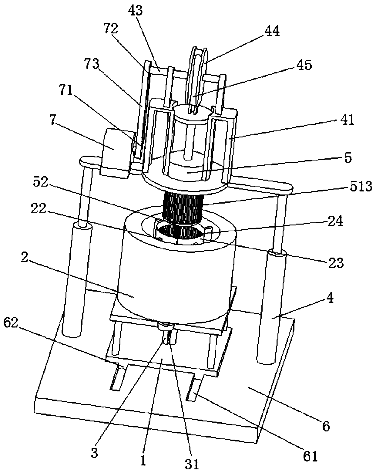
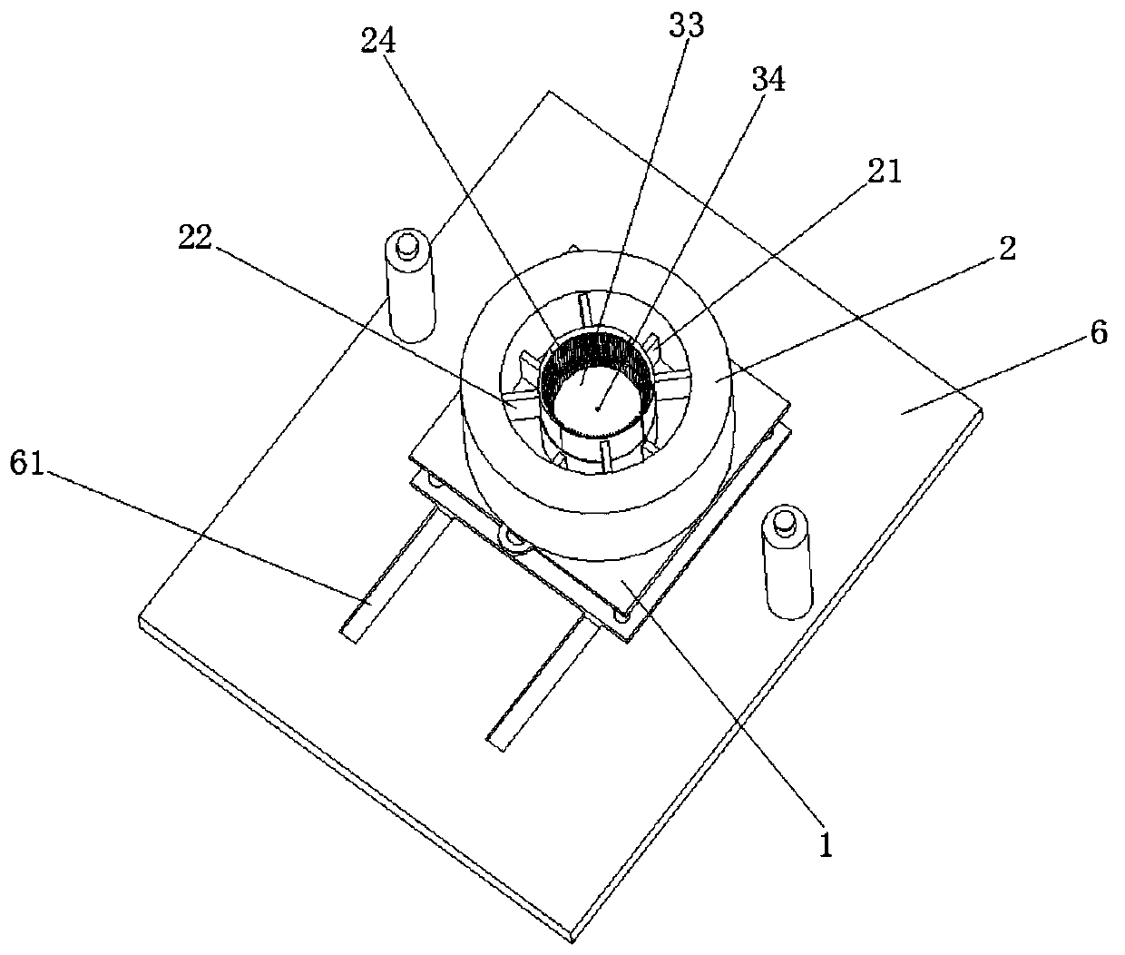
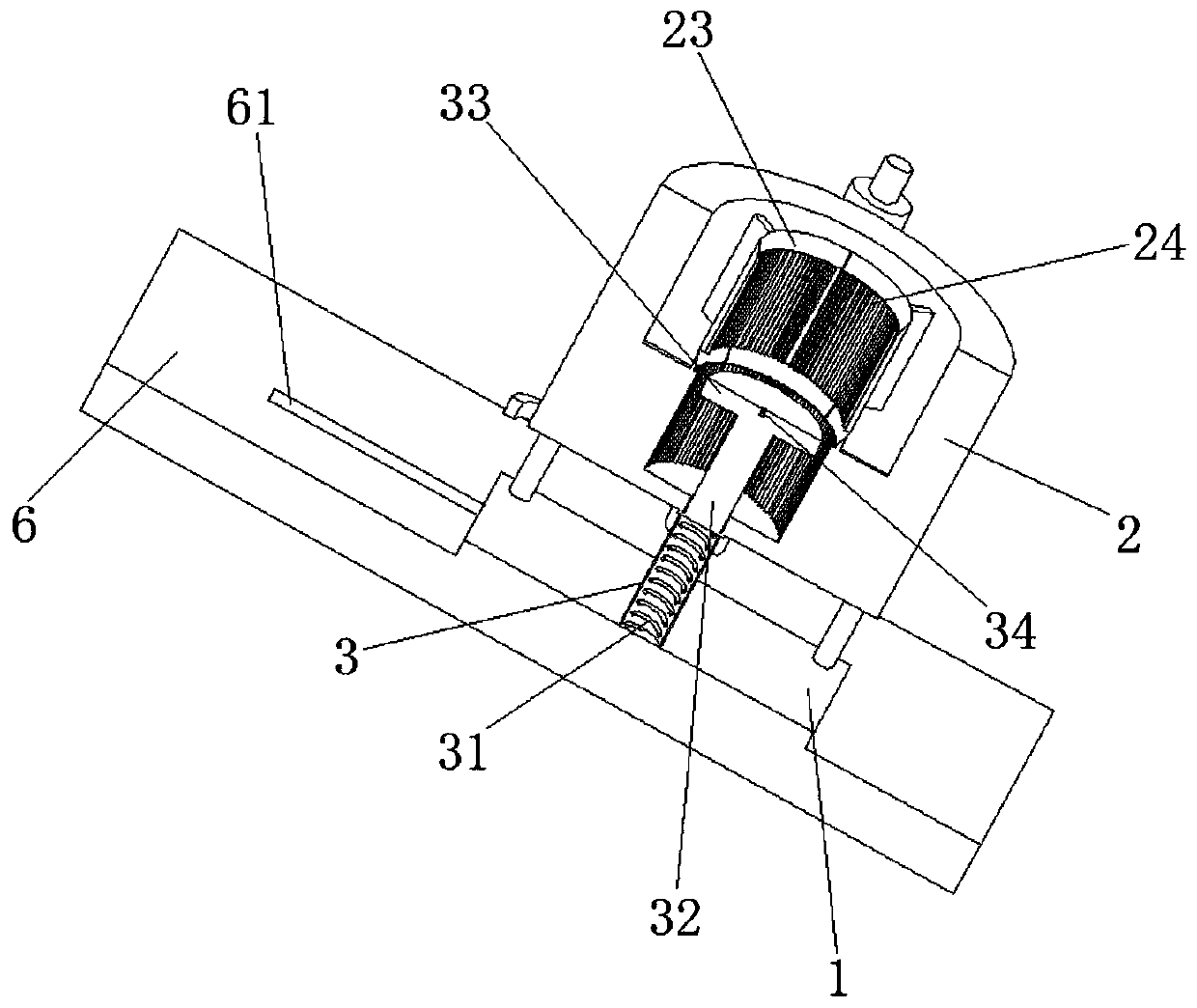
[0024] Such as Figure 1 to Figure 5 As shown, a precision processing device after forming an electric motor alloy shell includes a bracket 1, a fixed base 6 is provided at the bottom of the bracket 1, and chute 61 is symmetrically opened on the fixed base 6, and chute 61 is inserted with The slider 62, the top of the slider 62 is fixedly connected with the bottom of the bracket 1, the fixed base 6 is used for fixing, and the sliding groove 61 cooperates with the slider 62 to realize the movement of the bracket 1, which is convenient for placing and collecting the alloy shell.

[00...


PUM


Abstract

The invention relates to the field of casting processing, in particular to a precision processing device of a formed electric motor alloy shell. The precision processing device of the formed electricmotor alloy shell comprises a bracket, the top of the bracket is fixedly connected with a fixed slot, first telescopic frames are symmetrically inserted on the inner side of the fixed slot, second telescopic frames are symmetrically inserted on the inner side, located above the first telescopic frames, of the fixed slot, and the first telescopic frames and the second telescopic frames are arrangedin a staggered mode. One ends of the first telescopic frames and the second telescopic frames are fixedly connected with clamping plates, the sides of the clamping plates are fixedly connected with aplurality of first scraping strips, one ends of the first telescopic frames and the second telescopic frames inserted in the fixed slot are fixedly connected with first springs, a telescopic groove is fixedly connected to the bracket and located at the bottom of the fixed slot, a second spring is inserted in the telescopic groove, and a telescopic rod is inserted in the telescopic groove and located at the top of the second spring. The precision processing device of the formed electric motor alloy shell has simple structure, precise treatment can be carried out on the inner wall and the outerwall of the electric motor alloy shell at the same time, and the precision processing device of the formed electric motor alloy shell is suitable for popularization.

Description

technical field [0001] The invention relates to the field of electric motor processing, in particular to a precision processing device after forming an alloy shell of an electric motor. Background technique [0002] An electric motor is also called an electric motor. It is an electrical device that can convert electrical energy into mechanical kinetic energy and drive other devices. Its main structure is composed of a stator and a rotor. Generally, the stator and the rotor need to be fixed in an alloy shell. These alloy shells are basically made by casting process. After casting, the surface of the alloy shell is usually uneven and some debris remains, which is not conducive to the installation of the stator and rotor. [0003] In response to the above problems, the existing method is to grind the cast alloy shell for precision treatment, but the conventional grinding method requires manual operation, which is time-consuming and laborious, reduces production efficiency, and ...

Claims


Application Information

Patent Timeline
Patent Type & Authority Applications(China)
IPC IPC(8): B24B9/04B24B47/16B24B41/04B24B27/00B24B41/02B24B41/06H02K15/14
CPCB24B9/04B24B27/0076B24B41/02B24B41/04B24B41/067B24B47/16H02K15/14
Inventor 朱彬祥李超
Owner CHANGZHOU LEKVA ELECTRONICS CO LTD
Learn More