Special positioning and clamping equipment for assembling wind power boundary beam

A side beam and clamping technology, which is applied in the direction of workpiece clamping devices and manufacturing tools, can solve the problems of low workpiece positioning accuracy, slow workpiece disassembly speed, and affecting workpiece processing quality.

Inactive Publication Date: 2020-07-07
TIANJIN BAOLAI PRECISION MACHINERY
View PDF0 Cites 0 Cited by
  • Summary
  • Abstract
  • Description
  • Claims
  • Application Information

AI Technical Summary

Problems solved by technology

Due to the long length and large size of the wind power side beams, and there is no special workpiece pressing and positioning equipment at present, the staff usually can only use ordinary pressure plates to position the workpiece, which brings great inconvenience to the staff's operation. Not only does it lead to slow disassembly and assembly of the workpiece, but also the positioning accuracy of the workpiece is not high, which affects the processing quality of the workpiece, leads to more rework, and reduces work efficiency

Method used


Image

  • Special positioning and clamping equipment for assembling wind power boundary beam
  • Special positioning and clamping equipment for assembling wind power boundary beam
  • Special positioning and clamping equipment for assembling wind power boundary beam

Examples


Embodiment Construction

[0018] The embodiments of the present invention will be described in detail below in conjunction with the accompanying drawings; it should be noted that the embodiments are illustrative, not restrictive, and cannot limit the protection scope of the present invention.

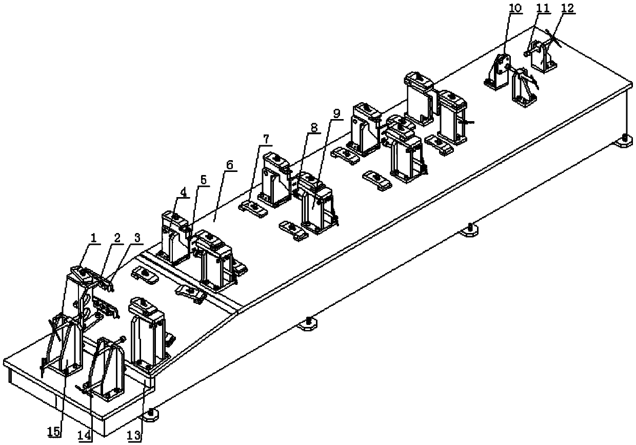
[0019] A positioning clamping device specially used for wind power side beam assembly, including a workbench 6, a left end plate tightening mechanism, a lower pressure plate 7, a vertical plate positioning mechanism, a vertical plate tensioning mechanism, an upper pressure plate 1 and a rear fork plate positioning and tightening mechanism.

[0020] A vertical positioning surface 13 is made on the left side of the workbench upper surface, and the left end plate jacking mechanism is installed on the workbench upper surface on the left side of the positioning surface. The left end plate tightening mechanism is two symmetrically arranged, and each left end plate tightening mechanism includes a support 15 and a top c...


PUM


Abstract

The invention relates to special positioning and clamping equipment for assembling a wind power boundary beam. The special positioning and clamping equipment comprises a workbench, a left end plate jacking mechanism, lower pressing plates, vertical plate positioning mechanisms, vertical plate jacking mechanisms, upper pressing plates and a rear fork plate positioning and jacking mechanism, whereina vertical positioning surface is formed in a left side of an upper surface of the workbench; the left end plate jacking mechanism is installed on the upper surface of the workbench on a left side ofthe positioning face, a plurality of lower pressing plates are installed on the upper surface of the workbench on a right side of the positioning face, the vertical plate positioning mechanisms and the vertical plate jacking mechanisms are installed on the workbench, and the upper pressing plate is installed on the upper end face of each vertical plate positioning mechanism and the upper end faceof each vertical plate jacking mechanism; and the rear fork plate positioning and jacking mechanism is mounted on the right side of the upper surface of the workbench. The special positioning and clamping equipment for assembling the wind power boundary beam is scientific in design, reasonable in structure, convenient to operate and high in practicability, is simple and convenient to use and easyto master, and can bring convenience to worker; and the working efficiency can be improved, and the machining quality of a workpiece is guaranteed.

Description

technical field [0001] The invention relates to the technical field of production and processing of wind power generators, in particular to a positioning clamping device specially used for assembling wind power side girders. Background technique [0002] The side beam of the wind turbine needs to be assembled and spot-welded during the production process, that is, the staff will assemble and spot-weld the various parts of the side beam. Due to the long length and large size of the wind power side beams, and there is no special workpiece pressing and positioning equipment at present, the staff usually can only use ordinary pressure plates to position the workpiece, which brings great inconvenience to the staff's operation. Not only does it lead to slow disassembly and assembly of the workpiece, but also the positioning accuracy of the workpiece is not high, which affects the processing quality of the workpiece, causes more rework, and reduces work efficiency. Contents of th...

Claims


Application Information

Patent Timeline
Patent Type & Authority Applications(China)
IPC IPC(8): B25B11/02
CPCB25B11/02
Inventor 崔雅臣张涛崔超崔越崔文来崔建涛李绍功李绍德崔雅海
Owner TIANJIN BAOLAI PRECISION MACHINERY
Why Eureka
Try Eureka