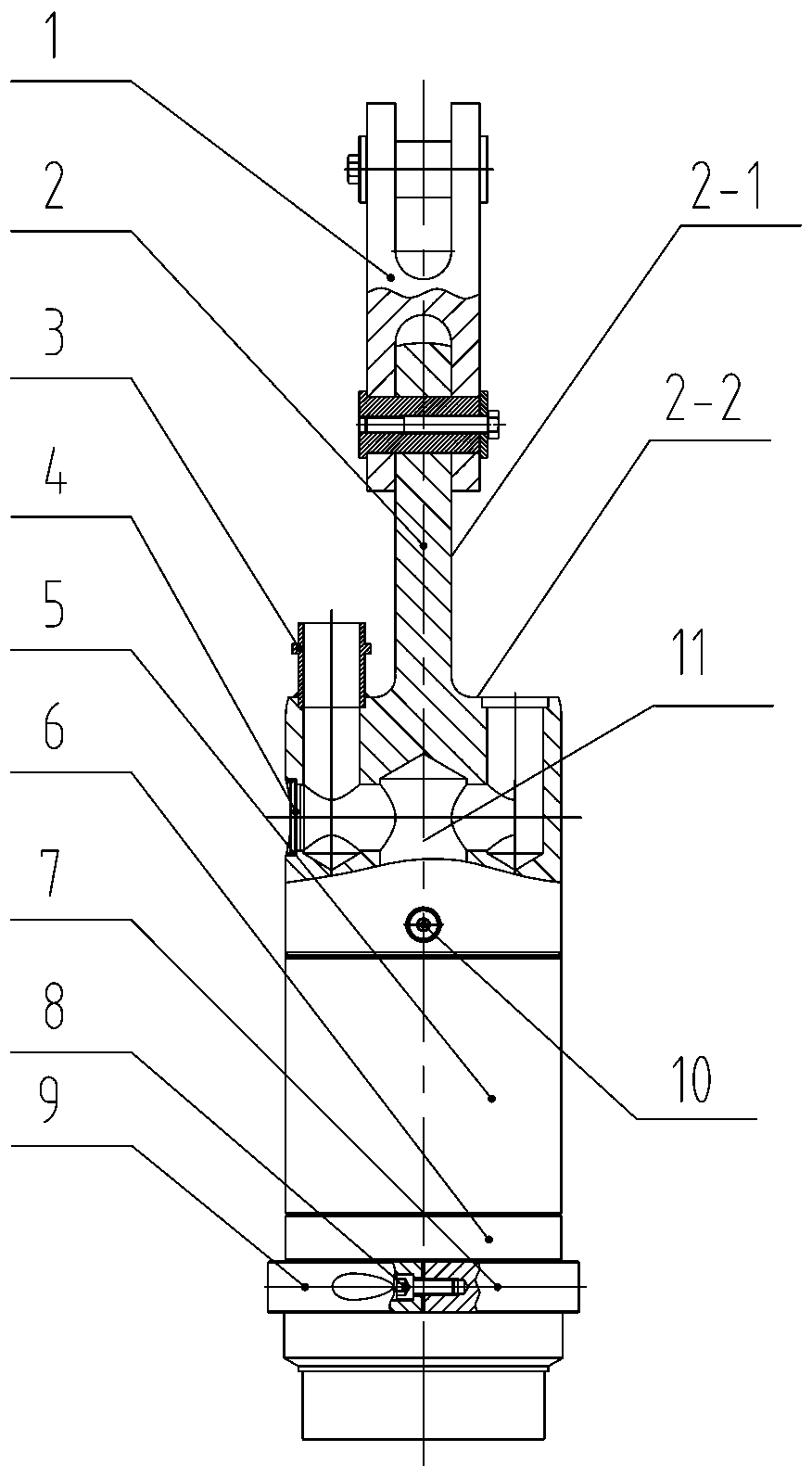
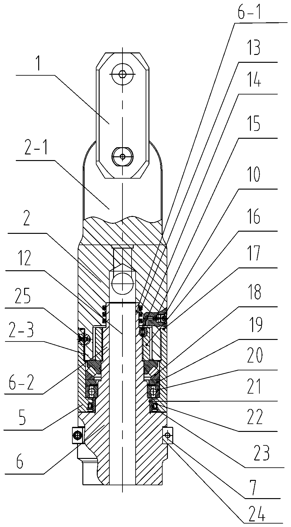
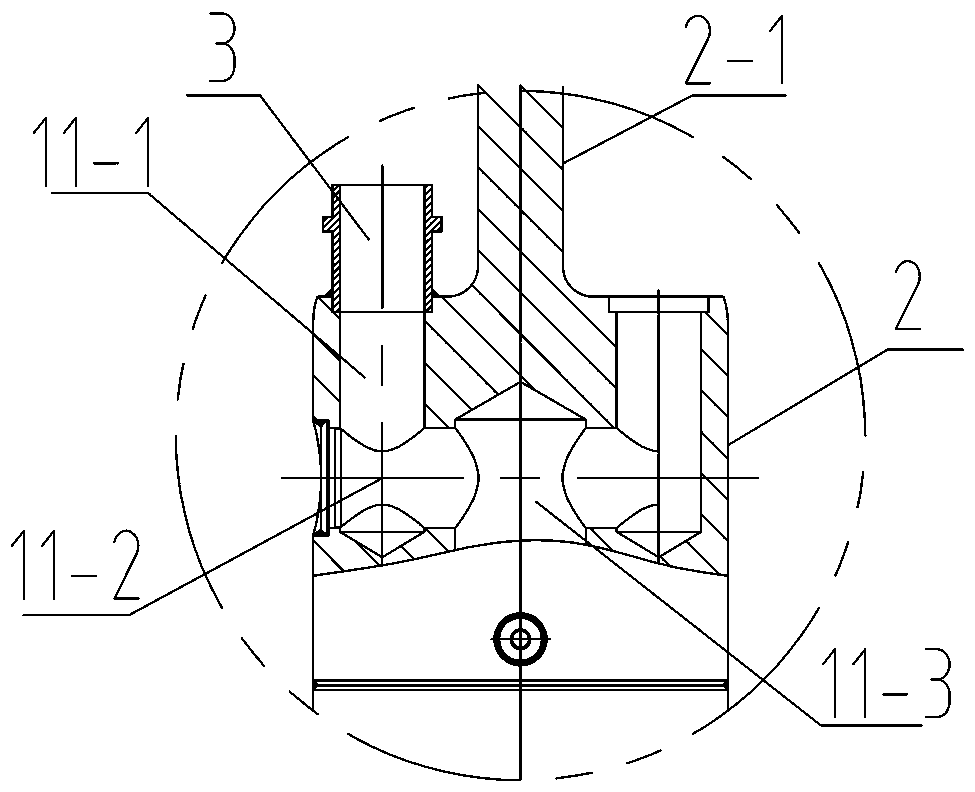
Rotary drilling rig elevator with gas transmission channel therein

A technology for rotary drilling rigs and gas transmission, which is applied in the direction of drill pipes, drill pipes, mechanical equipment, etc., and can solve problems such as high-pressure gas transmission that cannot solve large flows

Pending Publication Date: 2020-07-07
徐州海润行知重工机械有限公司
View PDF0 Cites 1 Cited by
  • Summary
  • Abstract
  • Description
  • Claims
  • Application Information

AI Technical Summary

Problems solved by technology

In the prior art, some lifters can have built-in small-diameter channels, but they can barely realize the transmission o

Method used


Image

  • Rotary drilling rig elevator with gas transmission channel therein
  • Rotary drilling rig elevator with gas transmission channel therein
  • Rotary drilling rig elevator with gas transmission channel therein

Examples


Embodiment Construction

[0024] The technical solutions in the embodiments of the present invention will be clearly and completely described below in conjunction with the accompanying drawings. Obviously, the described embodiments are only some, not all, embodiments of the present invention. The following description of at least one exemplary embodiment is merely illustrative in nature and in no way taken as limiting the invention, its application or uses. Based on the embodiments of the present invention, all other embodiments obtained by persons of ordinary skill in the art without creative work fall within the protection scope of the present invention.

[0025] Techniques, methods and devices known to those skilled in the art may not be discussed in detail, but where appropriate, such techniques, methods and devices should be considered part of the Authorized Description.

[0026] Such as Figure 1-4 The lifter of a rotary drilling rig with a built-in gas transmission channel shown includes an upp...


PUM


Abstract

The invention discloses a rotary drilling rig elevator with a gas transmission channel therein, and belongs to the technical field of rotary drilling rigs. The rotary drilling rig elevator comprises an upper connecting body, a middle connecting body and a lower connecting body, wherein a board body is arranged on the upper connecting body; gas joints are connected on shoulder parts of one or two sides of a lug plate; a gas channel upper section which communicates with the gas joints is manufactured inside the upper connecting body; the lower end of the upper connecting body is fixedly connected to the middle connecting body through a threaded joint; a cylinder core of the lower connecting body extends in from the lower part of the middle connecting body and extends into the upper connecting body; an inner nut is arranged on the upper part of the cylinder core of the lower connecting body; a bearing assembly is arranged between the middle connecting body below the inner nut and the lower connecting body; a sealing joint part of the lower connecting body and the upper connecting body are in dynamic sealing; a gas channel lower section which is axially through is arranged on the middle inside the lower connecting body; and the gas channel lower section is in butt joint to the gas channel upper section to define the gas transmission channel. The rotary drilling rig elevator can realize load transfer under a relative rotation working condition, and also can realize high-pressure gas transmission.

Description

technical field [0001] The invention relates to a lifter for a rotary drilling rig, belonging to the technical field of rotary drilling rigs. Background technique [0002] The structure of the lifter of the existing conventional rotary drilling rig is shown in the accompanying drawing Figure 5 As shown, the upper end is slotted and connected with the main hoisting wire rope of the drilling rig through the pin shaft, and the lower end is slotted and connected with the drill pipe through the pin shaft. One function of the lifter is to transmit the lifting force of the wire rope. With the retraction and release of the main hoisting wire rope, it drives the rotary drilling drill pipe and the drill bit to lift and lower; the other function is to isolate the rotation of the drill pipe during work, that is, the lifter When the power head rotates, the drill bit bears the torsional force of the drill pipe when drilling and throwing soil, and the lifter removes the torsional stress t...

Claims


Application Information

Patent Timeline
IPC IPC(8): E21B19/02F16L27/087F16L39/06
CPCE21B19/02F16L27/087F16L39/06
Inventor 胡殿立朱存立
Owner 徐州海润行知重工机械有限公司
Why Eureka
Try Eureka