Scanning driver, optical fiber scanning device and projection display equipment

A technology of scanning driver and optical fiber, applied in the field of scanning imaging, can solve the problems of low pixel utilization rate and difficult matching of image sources, etc.

Inactive Publication Date: 2020-07-07
CHENGDU IDEALSEE TECH
View PDF6 Cites 1 Cited by
  • Summary
  • Abstract
  • Description
  • Claims
  • Application Information

AI Technical Summary

Problems solved by technology

[0005] If the fiber optic scanner is used in the field of scanning imaging, since the image source is generally a rectangular area, the spiral scanning method has many disadvantages, such as: it is not easy to match with the image source, the pixel utilization rate is not high, etc.

Method used


Image

  • Scanning driver, optical fiber scanning device and projection display equipment
  • Scanning driver, optical fiber scanning device and projection display equipment
  • Scanning driver, optical fiber scanning device and projection display equipment

Examples


Embodiment Construction

[0045] The following will clearly and completely describe the technical solutions in the embodiments of the present invention with reference to the accompanying drawings in the embodiments of the present invention. Obviously, the described embodiments are only some, not all, embodiments of the present invention. Based on the embodiments of the present invention, all other embodiments obtained by persons of ordinary skill in the art without creative efforts fall within the protection scope of the present invention.

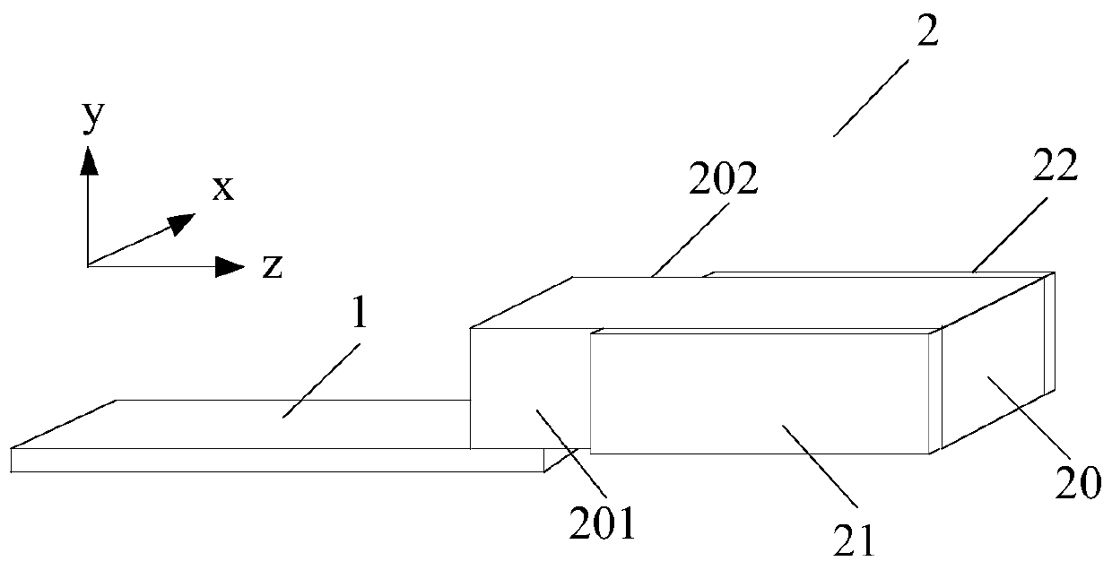
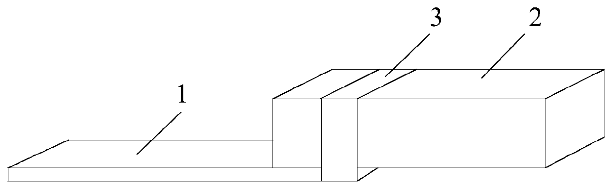
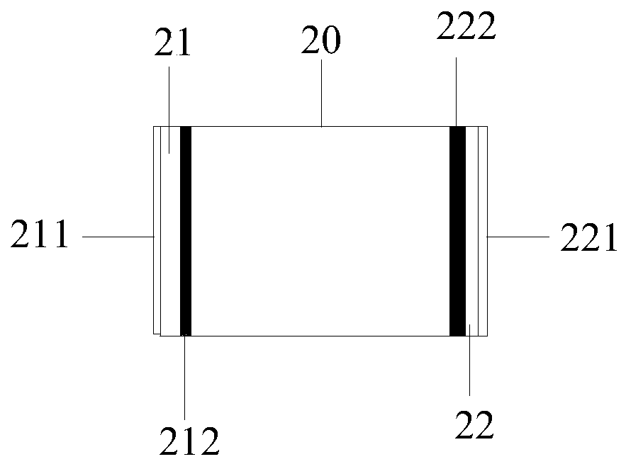
[0046] Please refer to figure 1 , figure 1The structural diagram of the scan driver provided by the embodiment of the present invention, the optical scanner includes the first actuating part 1 as the slow axis and the second actuating part 2 as the fast axis; the first actuating part 1 can drive the second actuating part 1 The moving part 2 vibrates in the first direction, and the second actuating part 2 can vibrate in the second direction. The second actuating p...


PUM


Abstract

The invention discloses a scanning driver, an optical fiber scanning device and projection display equipment; the scanning driver comprises a first actuating part as a slow axis and a second actuatingpart as a fast axis; the first actuating part can drive the second actuating part to vibrate in a first direction, and the second actuating part can vibrate in a second direction; the second actuating part comprises a base body and a piezoelectric driving piece, and the base body comprises a first surface and a second surface which are oppositely arranged; the piezoelectric driving piece includea first piezoelectric driving sheet disposed on the first surface and a second piezoelectric driving sheet disposed on the second surface. According to the scheme, a novel scanning driver structure isprovided, the structure is particularly suitable for achieving grid type scanning and control, and therefore compared with a spiral scanner, the scanning driver structure has the advantages of beingeasy to match with a rectangular video and high in pixel utilization rate.

Description

technical field [0001] The invention relates to the field of scanning imaging, in particular to a scanning driver, an optical fiber scanning device and projection display equipment. Background technique [0002] The fiber optic scanner can scan according to the designer's pre-designed trajectory to output images, thereby replacing traditional LCD (Liquid Crystal Display; liquid crystal display), LCOS (Liquid Crystal on Silicon; liquid crystal with silicon / silicon-based liquid crystal) and OLED (Organic Light-Emitting Diode; Organic Light-Emitting Diode) image source, etc., integrated into HMD (Head Mount Display; head-mounted display), micro projection equipment and vehicle HUD (Head Up Display; head-up display) and other equipment, and can also Used in medical endoscopes, scanning tunneling microscopes and other equipment, the application range is very wide. [0003] At present, the main application fields of fiber optic scanners are endoscopes. The working principle of th...

Claims


Application Information

Patent Timeline
Patent Type & Authority Applications(China)
IPC IPC(8): G02B26/10H02N2/00
CPCG02B26/103H02N2/0075
Inventor 王重阳岳忠宇姚长呈
Owner CHENGDU IDEALSEE TECH
Why Eureka
Try Eureka