
Jig for welding cable on probe connector

A technology for welding cables and connectors, which is applied in connection, circuits, electrical components, etc., can solve problems such as low production efficiency, low welding accuracy, and difficulty in ensuring product quality, and achieves the effect of compact structure and simple structure

Inactive Publication Date: 2020-01-03
王清国
View PDF10 Cites 0 Cited by
  • Summary
  • Abstract
  • Description
  • Claims
  • Application Information

AI Technical Summary

Problems solved by technology

Cables need to be connected to the probe connectors. In current production, this process is manually welded. The production efficiency is low, the welding accuracy is not high, and the quality of the products is difficult to be guaranteed.

Method used


Image

  • Jig for welding cable on probe connector
  • Jig for welding cable on probe connector
  • Jig for welding cable on probe connector

Examples


Embodiment Construction

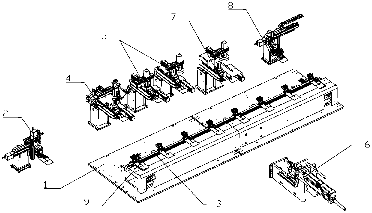
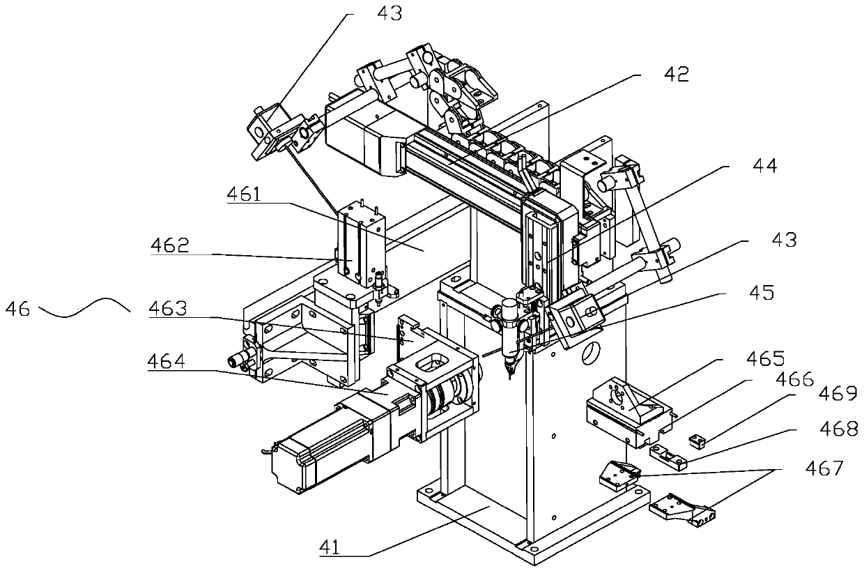
[0020] Such as figure 1 As shown, a cable welding device for a probe connector includes a frame 1 and a loading and conveying device 2 installed on the frame 1, a jig conveying device 3, a tin coating device 4, a laser welding device 5, and a butt welding device 6. The visual inspection device 7 and the unloading and conveying device 8; the feeding and conveying device 2 and the unloading and conveying device 8 are located at both ends of the fixture conveying device 3, and the tin coating device 4 and the laser welding device 5 are arranged on the fixture conveying device 3 The side of the corresponding jig conveying device 3; along the processing direction, the laser welding device 5 is located behind the tin coating device 4, and two sets of laser welding devices 5 are arranged behind the tin coating device 4; the butt welding device 6 is located in the jig conveying device The other side of 3 corresponds to the jig conveying device 3 , and the visual inspection device 7 is...


PUM


Abstract

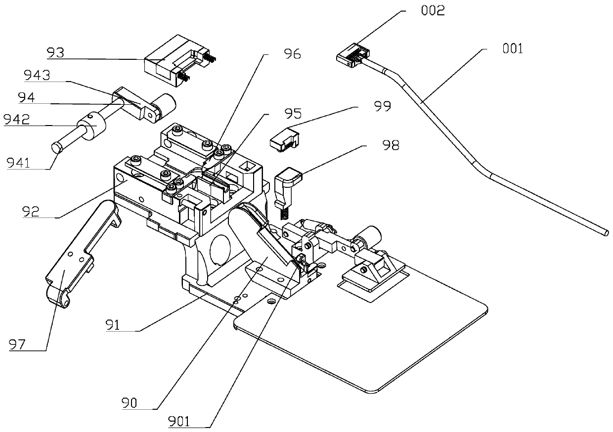
The invention relates to a jig for welding a cable on a probe connector. The jig comprises a pedestal, a sliding base, a positioning base, a clamping assembly, a cable positioning base, a side blocking base, a pressing plate, an unlocking block, a locking block and a cable base. The sliding base is fixedly arranged on the pedestal. The positioning base is movably connected into the sliding base. Anotch is formed in the side of the positioning base. The side blocking base is fixedly arranged in the middle of the sliding base. A through slot is formed in the side of the side blocking base. Theclamping assembly is hinged to the end of the sliding base. The pressing plate is rotationally connected with the sliding base. The locking block is horizontally arranged in the sliding base in a matching manner, a buckle is arranged at the outer end of the locking block, a vertical through slot is formed in the side of the locking block, and a spring is arranged at the bottom end of the locking block. The unlocking block is vertically arranged in the sliding base in a matching manner, a spring is arranged at the lower end of the unlocking block, a wedge-shaped notch is formed in the side of the unlocking block, and the unlocking block is arranged in the vertical through slot in the side of the locking block in a matching manner. The jig can complete tin soldering and butt welding operations, can achieve higher production efficiency, and is accurate in positioning and reliable in clamping.

Description

technical field [0001] The invention relates to the technical field of electronic device production, in particular to a jig for probe connector welding cables. Background technique [0002] Connectors are generally used to transmit current and electrical signals. They are widely used in computers, smart phones, smart bracelets, smart watches, tablet computers, etc. Watches, the connectors used inside it also require specific performance. The probe connector includes an insulating shell, a metal casing assembled in the insulating casing, a probe assembled in the metal casing, and a compression spring. The probes are often arranged in multiple rows, and cables are welded on the metal casing. The open core is connected to the metal sheath by soldering, and a sheet metal part is clamped on the insulating sheath of the cable. cable. [0003] The State Intellectual Property Office of China has published a patent with the publication number CN206388928U and the patent name is a ...

Claims


Application Information

Patent Timeline
Patent Type & Authority Applications(China)
IPC IPC(8): H01R43/02
CPCH01R43/02H01R43/0263
Inventor 王清国王杨玲杨阿青
Owner 王清国
Learn More