Antenna device and radar

An antenna device and antenna technology, which are applied in the direction of the antenna, antenna components, and antenna grounding switch structure connection, etc., can solve the problems of uneliminated and unfavorable reduction of antenna pattern jitter, etc.

Pending Publication Date: 2020-07-07
福瑞泰克智能系统有限公司
View PDF12 Cites 2 Cited by
  • Summary
  • Abstract
  • Description
  • Claims
  • Application Information

AI Technical Summary

Problems solved by technology

This invention is aimed at the reflected wave from the antenna surface. The invention changes its direction through the electromagnetic reflection surface, but it does not eliminate it, which is not conducive to reducing the jitter of the antenna pattern

Method used


Image

  • Antenna device and radar
  • Antenna device and radar
  • Antenna device and radar

Examples


Embodiment 1

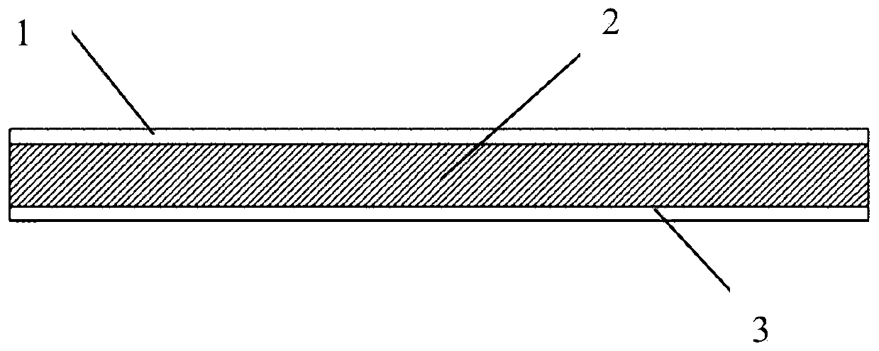
[0034] Such as figure 1 shown

[0035] The sectional view of the radar antenna device of the technical solution is composed of a ground layer 3, a dielectric layer 2 and an antenna layer 1, and both the antenna layer and the ground layer are copper-clad layers.

[0036] The copper clad layer of the antenna is subjected to electrochemical treatment to obtain an antenna structure and a checkerboard structure.

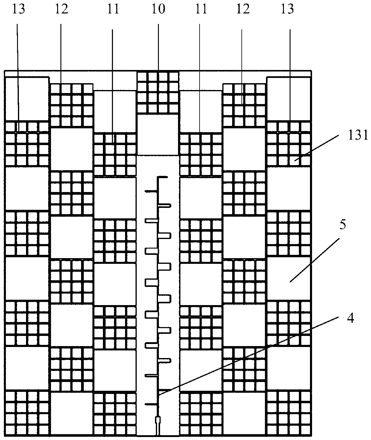
[0037] figure 2 Shown is a schematic diagram of the antenna structure.

[0038] The size of the checkerboard patch gradually increases from the column where the antenna is located to the two sides, and the checkerboard structure in the antenna device is arranged alternately by PECs and AMCs.

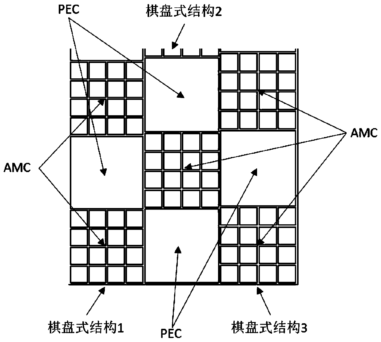
[0039] Such as image 3 As shown, the checkerboard structure is composed of PEC and AMC. PEC is composed of a whole metal patch, and AMC is composed of n*n regular polygonal patches.

[0040] PEC (Perfect Electric Conductor) is an ideal electrical conductor, which is a whole p...


PUM


Abstract

The embodiment of the invention provides an antenna device capable of reducing directional diagram jitter. The antenna device is composed of a ground layer, a dielectric layer and an antenna layer. The antenna layer comprises a comb-shaped antenna and a chessboard structure distributed around the comb-shaped antenna. The chessboard structure is composed of patches, and each column and each transverse row are formed by arranging PECs and AMCs in a staggered mode. And the PEC and the AMC are both regular polygon patches. The chessboard type structure can reduce the radar scattering cross sectionof the surface of the antenna and reduce the jitter of the directional diagram of the radar antenna.

Description

Technical field: [0001] The invention belongs to the technical field of microwave antennas, in particular to an antenna device with a checkerboard structure Background technique: [0002] Radar is one of the core sensors in the car's intelligent driving system, and its performance plays a vital role in car safety. [0003] The electromagnetic waves emitted by traditional automotive radars will form multiple reflections between the radome and the antenna surface, which will cause jitter in the antenna pattern and affect the stability of the system. In the prior art, the traditional automotive radar antenna has a relatively large jitter in the directional diagram, and the FOV of the radar is unstable. In the closest prior art, Patent No. 201600734286 introduces a technical solution, the technical solution is mainly by providing a reflective part on the antenna part, and the reflective part is arranged around the above-mentioned antenna part through the reflective part, and ha...

Claims


Application Information

Patent Timeline
Patent Type & Authority Applications(China)
IPC IPC(8): H01Q1/38H01Q1/32H01Q1/50G01S7/02
CPCH01Q1/38H01Q1/50H01Q1/3233G01S7/02
Inventor 赵宇楠范朝洋
Owner 福瑞泰克智能系统有限公司
Why Eureka
Try Eureka