Direct-buried gas filter

A filter and direct-buried technology, which is applied in the field of filters, can solve the problems of large vertical size, increased construction volume, and difficult installation, so as to reduce the vertical size and buried depth, and reduce the amount of buried construction , The effect of reducing the difficulty of installation

Active Publication Date: 2020-07-10
江苏盛伟燃气科技有限公司
View PDF6 Cites 7 Cited by
  • Summary
  • Abstract
  • Description
  • Claims
  • Application Information

AI Technical Summary

Problems solved by technology

[0002] In the gas pipeline network, traditional regional pressure regulating stations are usually set up on the ground, which requires the construction of station buildings for the management and maintenance of pressure regulators and filters and other equipment, which not only takes up a lot of land resources and ground space, and not conducive to urban planning
In order to solve this problem, there is currently a method in the field of burying pressure regulators, filters and other equipment vertically underground and setting a control port at the upper end, but there are large gaps in the gas inlet and outlet of the existing buried gas filter. The height difference results in a large vertical dimension, which requires a large direct burial depth when buried, and the elevation of the gas inlet and outlet must be adjusted through elbows to connect with the buried gas pipelines on both sides, which not only increases the construction volume , and the installation is difficult
In addition, the existing buried gas filter can only filter out solid particles in the gas, but cannot effectively filter out the moisture in the gas. After the moisture condenses into water droplets, it is easy to cause damage to pipeline components such as ice blockage of the voltage regulator signal tube. phenomenon, which affects the safety and stability of the gas pipeline network operation

Method used


Image

  • Direct-buried gas filter
  • Direct-buried gas filter
  • Direct-buried gas filter

Examples


Embodiment Construction

[0023] First of all, it needs to be explained that the orientation words such as up, down, left, right, front, and back described in the present invention are only described according to the accompanying drawings, so as to facilitate understanding, and are not intended to limit the technical solution and scope of protection of the present invention. .

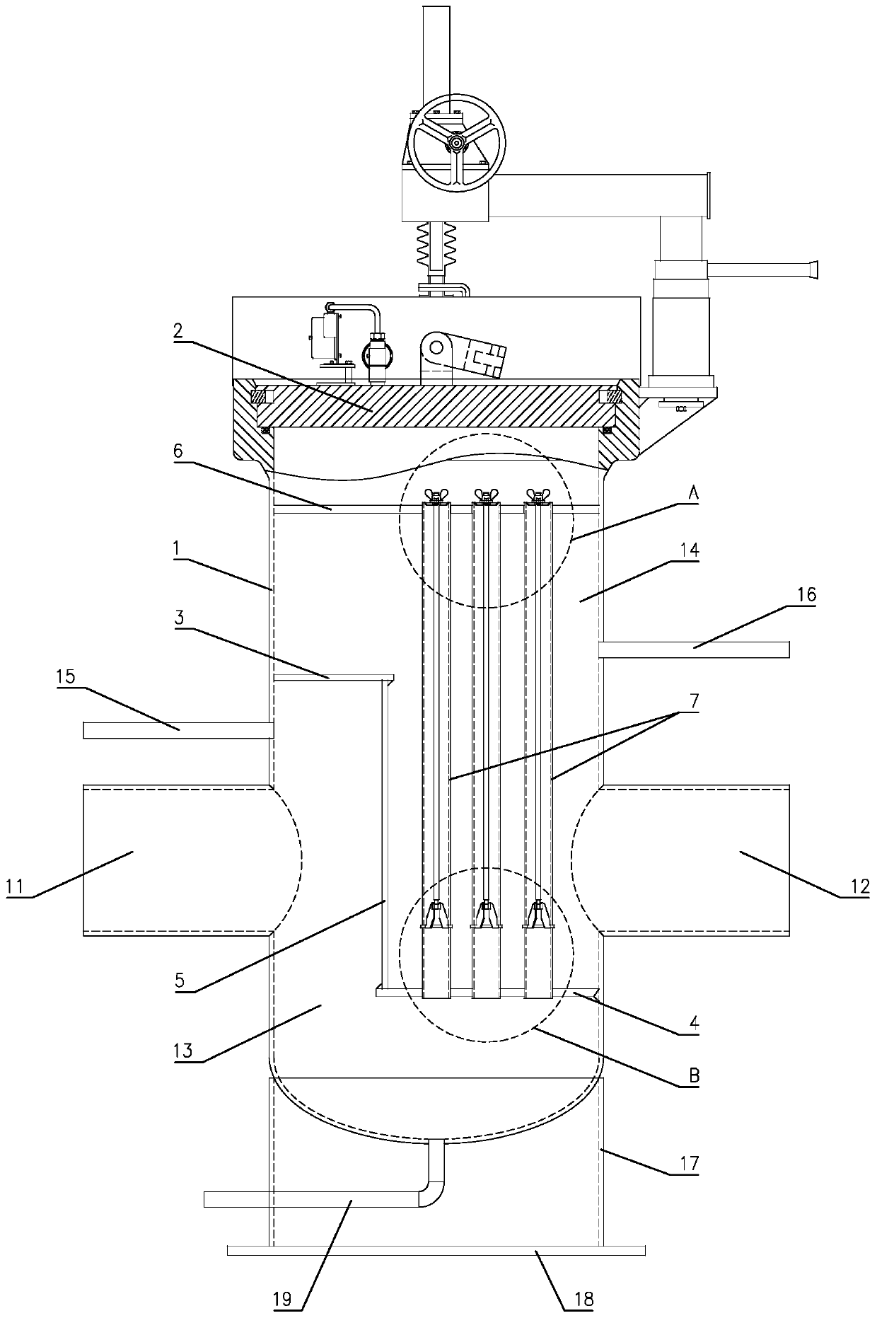
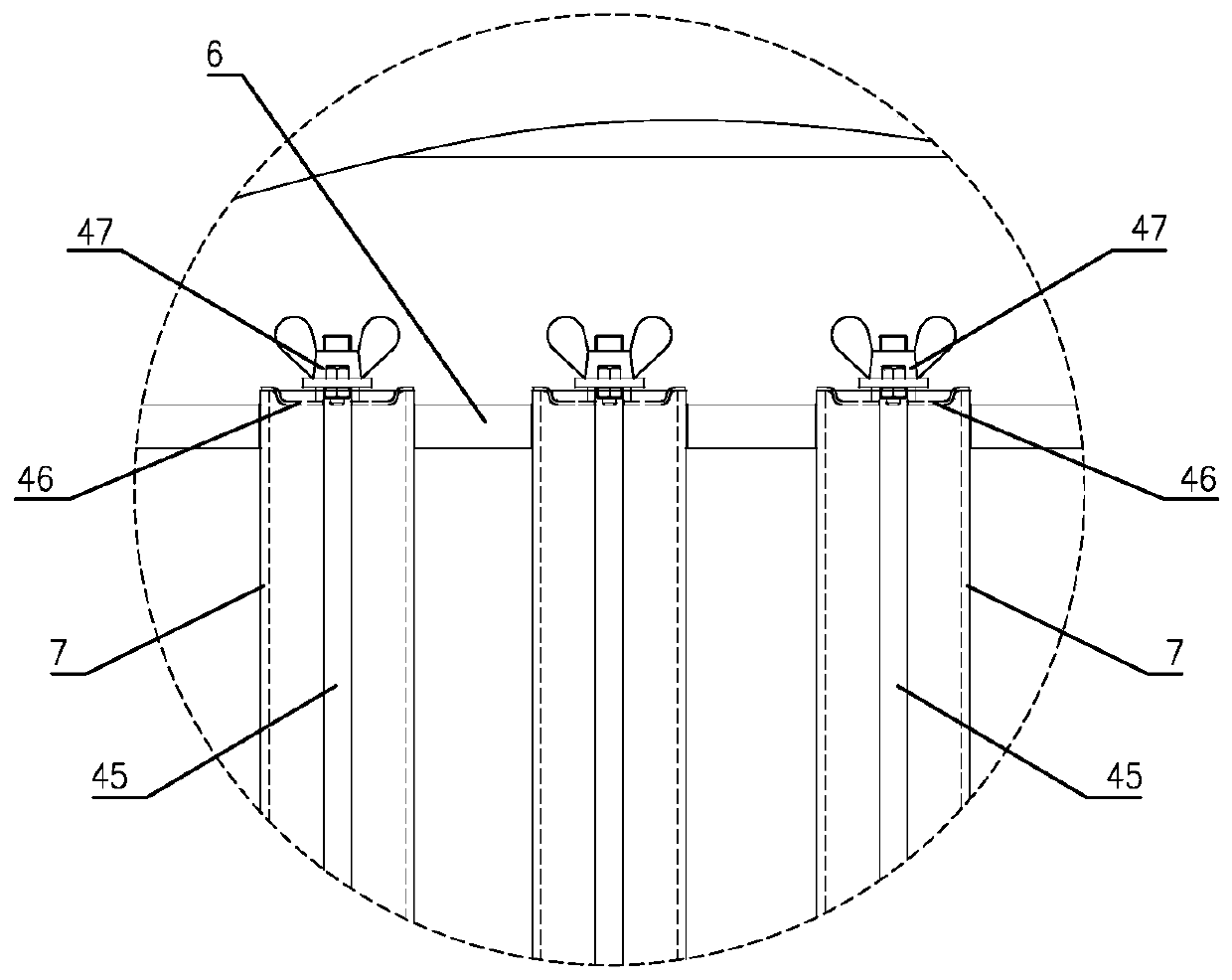
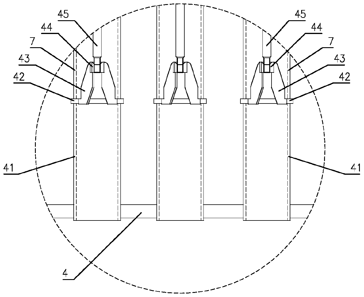
[0024] Such as Figure 1 to Figure 9 Shown is a specific embodiment of a direct-buried gas filter of the present invention, which includes a casing 1 with an open upper end and a quick-opening blind plate 2 installed at the opening of the casing 1 . An air inlet 11 and an air outlet 12 are correspondingly arranged on the left and right sides of the housing 1 , and the inner cavity of the housing 1 is divided into an air inlet chamber 13 and an air outlet chamber 14 by a baffle assembly. The baffle assembly specifically includes a left baffle 3, a right baffle 4 and a vertical baffle 5, the left baffle 3 is arranged horizontall...


PUM


Abstract

The invention discloses a direct-buried fuel gas filter. The gas filter comprises a shell and a quick-opening blind plate mounted at an opening in the upper end of the shell, an air inlet and an air outlet are correspondingly formed in the left and right sides of the shell; an inner cavity of the shell is divided into an air inlet cavity and an air outlet cavity through a baffle assembly, the baffle assembly comprises a left baffle, a right baffle plate and a vertical baffle plate, the left baffle plate is horizontally arranged and located on the upper side of the air inlet, the right baffle plate is horizontally arranged and located on the lower side of the air outlet, and the upper end and the lower end of the vertical baffle plate are correspondingly connected with the left baffle plateand the right baffle plate. A support plate which is located on the upper side of the air outlet and is in a horizontal state is further arranged in the inner cavity of the shell, a plurality of vertical coalescence filter elements are arranged between the support plate and the right baffle plate, the lower ends of inner holes of a coalescence filter elements are communicated with the air inlet cavity, and the upper ends of inner holes of the coalescence filter elements are closed. The gas filter has the advantages of being compact in structure, high in adaptability and good in filtering effect, the burial depth and the installation difficulty can be effectively reduced, moisture in gas can be filtered out, and the safety and reliability of gas pipe network operation and the gas quality of the tail end are enhanced.

Description

technical field [0001] The invention relates to a filter, in particular to a directly buried gas filter. Background technique [0002] In the gas pipeline network, traditional regional pressure regulating stations are usually set up on the ground, which requires the construction of station buildings for the management and maintenance of pressure regulators and filters and other equipment, which not only takes up a lot of land resources and ground space, And it is not conducive to urban planning. In order to solve this problem, there is currently a method in the field of burying pressure regulators, filters and other equipment vertically underground and setting a control port at the upper end, but there are large gaps in the gas inlet and outlet of the existing buried gas filter. The height difference results in a large vertical dimension, which requires a large direct burial depth when buried, and the elevation of the gas inlet and outlet must be adjusted through elbows to ...

Claims


Application Information

Patent Timeline
Patent Type & Authority Applications(China)
IPC IPC(8): B01D46/24B01D53/26B01D53/04C10L3/10
CPCB01D46/0036B01D46/0002B01D46/2414B01D53/261C10L3/106C10L3/101B01D46/60
Inventor 陈伟忠赵学朋李璋蔚蔡建姜大春于翠翠冯嘉
Owner 江苏盛伟燃气科技有限公司
Why Eureka
Try Eureka