Shearing mixing piece and vacuum mixer applying the same

A shear mixing and vacuum mixing technology, which is applied in mixers, mixers with rotary mixing devices, mixer accessories, etc., can solve the problems of increasing mixing time, waste of raw materials, and increasing feeding time, and achieve full mixing. Effect

Inactive Publication Date: 2020-07-10
上海斯太堡实业有限公司
View PDF6 Cites 5 Cited by
  • Summary
  • Abstract
  • Description
  • Claims
  • Application Information

AI Technical Summary

Problems solved by technology

[0006] 1. The built-in stirring device cannot quickly dissolve the added powder in other raw material liquids, so the above purpose can only be achieved by increasing the stirring time
[0007] 2. Before mixing, add all the raw materials to the mixer and then start vacuuming, which increases the feeding time, and for powder feeding, it is easy to fly during the feeding process, resulting in waste of raw materials and environmental pollution

Method used


Image

  • Shearing mixing piece and vacuum mixer applying the same
  • Shearing mixing piece and vacuum mixer applying the same
  • Shearing mixing piece and vacuum mixer applying the same

Examples


Embodiment 1

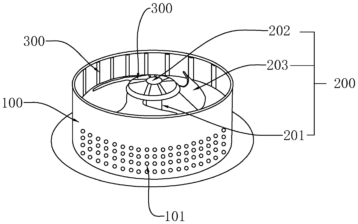
[0044] refer to figure 1, in order to achieve rapid shear mixing, a shear mixing element is provided, including a stator part 100 and a rotor part 200, the stator part 100 is sleeved on the outside of the rotor part 200 and fixed to each other, and the highest end of the rotor part 200 is lower than the stator part At the highest end of 100 , both the stator part 100 and the rotor part 200 are provided with spoilers 300 . The rotor part 200 is located inside the stator part 100, and the rotor part 200 runs at high speed to further break up the added powder, making it quickly dissolve in the liquid, and the stator part 100 further disturbs the solid-liquid mixture, further improving the dissolution effect. The spoiler part 300 is arranged on the inner peripheral surface of the stator part 100 , and a plurality of spoiler passage holes 101 are provided on the body of the stator part 100 . Under the high-speed agitation and shearing of the rotor part 200, the powder-liquid mixtu...


PUM


Abstract

The invention relates to the technical field of mixing equipment, and particularly discloses a shearing mixing piece and a vacuum mixer applying the same. The shearing mixing piece comprises a statorpart and a rotor part, the stator part sleeves the rotor part and the two parts are fixed to each other, a highest end of the rotor part is lower than a highest end of the stator part, the stator partand the rotor part are both provided with a turbulent flow part, and the vacuum mixer comprises the shearing mixing piece and a tank body. The invention has the beneficial effects that: the shearingmixing piece not only can realize a stirring effect, but also can shear added powder at a high speed, and rapid dissolution and sufficient mixing are achieved. According to the vacuum mixer, when liquid raw materials are added into a tank body, the vacuum equipment can be started, then feeding of powder is conducted through negative pressure in the tank body and intermittent opening of a materialsuction electromagnetic valve, the powder is directly sucked into the liquid to be mixed, and raw material waste caused by flying is avoided.

Description

technical field [0001] The invention relates to the technical field of mixing equipment, in particular to a mixing pipeline and a foam cleaning machine using the mixing pipeline. Background technique [0002] The mixer is a device for mixing various raw materials, such as powder and liquid. Due to the continuous development and high requirements of the process, a vacuum mixer has appeared now. [0003] Regarding the vacuum mixer, for example, the Chinese published patent (patent number: ZL201820209995.6, patent name: vacuum mixer for pesticide raw materials) specifically discloses the following technical scheme: a vacuum mixer for pesticide raw materials, which includes a vacuum pump (1 ), storage bin (2), filter screen (3), feed pipe (4), aggregate funnel (5), automatic door (6); vacuum pump (1) is installed in the storage bin (2) The top; the storage bin (2) is provided with a filter screen (3); the side of the storage bin (2) is provided with a feed pipe (4); the bottom ...

Claims


Application Information

Patent Timeline
Patent Type & Authority Applications(China)
IPC IPC(8): B01F1/00B01F7/18B01F13/06B01F15/02
CPCB01F21/10B01F27/90B01F33/70B01F35/71755B01F35/71805
Inventor 王小勇
Owner 上海斯太堡实业有限公司
Why Eureka
Try Eureka